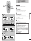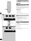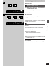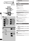
8
Getting started
AUDIO OUT
VIDEO
OUT
S-VIDEO
OUT
SUB-
WOOFER
L
R
AC IN
Y
C
B
C
R
COMPONENT
VIDEO OUT
AUDIO
IN
L
R
VIDEO
IN
C
B
C
R
Y
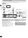
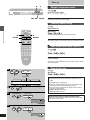
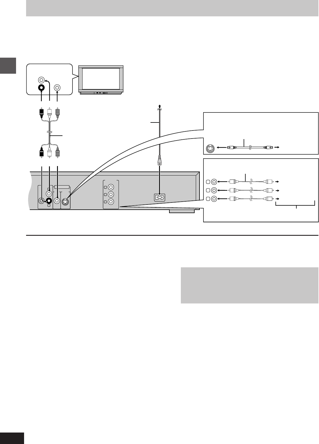
Connection to a television
These pages explain how to connect the unit to a television and set it up so you hear the audio through the television’s speakers. Connections and
procedures that enable you to enjoy more powerful sounds are described beginning on page 26.
[Before\connection]
³Disconnect the AC power supply cord.
³Refer to the television’s operating instructions.
To household
AC outlet
Audio/video cable (included)
Television
AC power supply cord
(included)
Back of the unit
[A] S VIDEO OUT terminal
The S-video terminal achieves a more vivid picture than the VIDEO
OUT terminal by separating the chrominance (C) and luminance (Y)
signals. (Actual results depend on the television.)
[B] COMPONENT VIDEO OUT terminal
Connection using these terminals outputs the color difference signals
(C
B/CR) and luminance signal (Y) separately in order to achieve high
fidelity in reproducing colors.
³The description of the component video input terminals depends on
the television or monitor (e.g. Y/P
B/PR, Y/B-Y/R-Y, Y/CB/CR). Con-
nect to terminals of the same color.
³After making this connection, change the black level for a better pic-
ture (á page 22, Video–Black Level Control).
Conserving power
This unit consumes approx. 2 W, even when it is turned off.
To save power when the unit is not to be used for a long time, unplug
it from the household AC outlet.
Connect Your Unit Directly To Your Tele-
vision.
Do not connect the unit through your video cassette recorder
when setting up your home entertainment system, because
the picture may not be played correctly due to the copy guard.
[A] S VIDEO OUT terminal
[B] COMPONENT VIDEO OUT terminal
S video cable (not included)
TV’s S video
input
terminal
Video cable (not included)
TV’s component video
input terminals
Y terminal
C
B terminal
C
R terminal
(Red)(White)(Yellow)
(Red)(White)(Yellow)


