


8
○
3
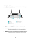
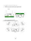
Alarm Input: Connect up to 12 alarm inputs, selectable between N.O./N.C. contacts.
○
4
Alarm Output: N.C or N.O type alarm out (form “C”).
○
5
RS232 socket: Connect this connector to RS232/RS485 compatible device.
○
6
GPS Data Input: Connect this connector to GPS receiver via GPS cable.
○
7
USB port: USB port recommended for connecting the USB mouse.
○
8
Power Input/Ignition Control In/Switched power out: 4 pins are reserved for power input; connect to
10V~36VDC power source. 1pin is for ignition control; connect to the other vehicle devices to avoid
excess power consumption at ignition. 1 pin is reserved for switched power out. The power source
used for this additional power output is 600 mA x 12VDC.
○
9
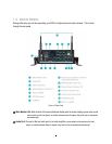
Video & Audio Inputs (12): Connect camera’s video output or other composite video source to the
video input connection.
Connect line level output of an audio preamplifier to the audio input connection corresponding to the
appropriate camera.
○
10
Camera Power Outputs (12): EMV1200 can provide power source to cameras, connect camera power
to this output by using the camera power cable. For the first 4 CH, the power source used is 300mA x
12VDC. For the rest, the power source used is 450mA x 12VDC.
○
11
Serial Port: Reserved port.
○
12
Control Port: Reserved port.
○
13
Call Monitor Out: This connector is used for the call monitor. This monitor can only display a full screen
picture.
○
14
802.11 b / g WiFi: Connection of the antenna.