


IR 102 Remote Control Kit • Installation and Operation
Installation and Operation, cont’d
1-10
IR 102 Remote Control Kit • Installation and Operation
1-11
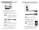
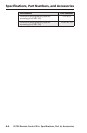
closure/RS-232 control port. This permits the IR 102 Rx Remote
Receiver to control the switcher. The pin assignments are listed
in the following table.
N
See the note for
d
.
N
Connect RS-232 or contact closure, but not both.
Remove the pins that are not needed.
Female (In)
5 1
9 6
Male (Out)
1 5
6 9
Pin RS-232 In Contact Closure
1 — Input #1
2 TX
—
—
3 RX
4 — Input #2
5 Gnd Gnd
6 —
7 —
8 —
9 —
Input #3
Input #4
Input #5
Input #6
Gnd
RS-232 Out
—
TX
RX
—
—
—
—
—
N
The cable used to connect the RS-232/Contact – Out
connector to a computer, control system, or contact
closure device may need to be modified by removing
pins or cutting wires. If unneeded pins are connected,
the system may "hang" (suspend communication
indefinitely).
For RS-232 control and IR control
, use a control cable with only
pins 2, 3, and 5 connected. If other pins are connected,
either cut the wires to the other pins if the cable has a hard-
shelled connector, or remove the other pins if the cable has
a molded plug.
For contact closure
, use a control cable with pins 2 and 3 not
connected. If the cable has pins 2 and 3 connected, cut the
wires to these pins if the cable has a hard-shelled connector,
or remove these pins if the cable has a molded plug.
f
RS-232 In connector — Plug the RS-232 input cable into this
9-pin D connector to permit a PC or control system to control
the switcher, even though the switcher’s RS-232 connector
is occupied by the IR 102 Rx Remote Receiver. The pin
assignments are shown in the table above.
Universal Remote
INPUT/OUTPUT SELECTION
1 2 3 4
5 6 7 8
9 0 +10 ENTER
IR 102
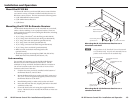
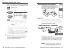
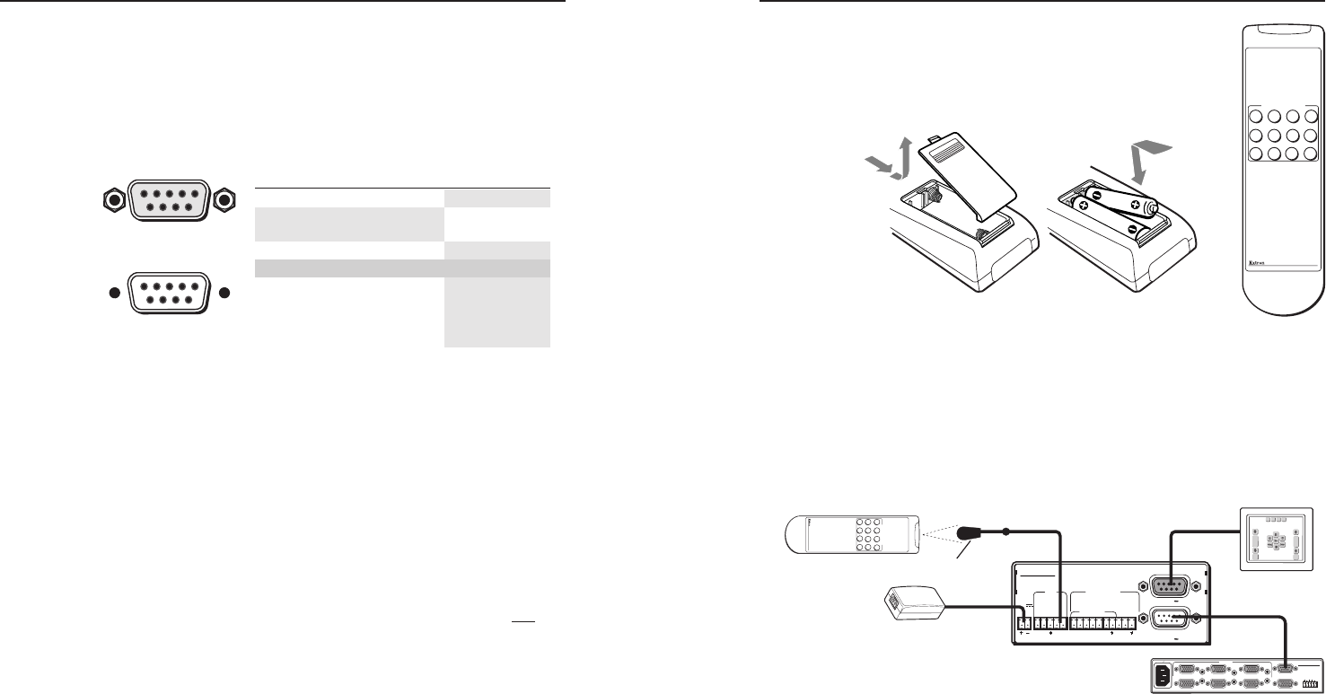
Installing Batteries in the Remote
The IR 102 Handheld Remote Control is shown at
right. Install two AAA batteries in the remote as
shown below. The battery compartment is in the
front, bottom side of the remote control.
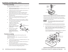
Operation
To select an input using the IR 102 remote control, aim the
handheld unit at the IR detector and press the numeric button
for the desired input. For switchers with ten or more inputs,
press the +10 key to add ten to the input number selected. For
example, to select input 17, press the +10 key, then the 7 key.
The maximum operating range is 30 feet.
Working together with a control system
IR 102 Rx UNIVERSAL IR REMOTE RECEIVER
RS-232/
CONTACT
OUT
RS-232
Tx Rx1 2 3 4 5+5
+12V
6
CONTROL OUT
IR IN
CONTACT
MOD
DEMOD
POWER
12V
.5A MAX
RS-232
IN
SW6 VGA Ars
REMOTE
100-240V 0.2A
INPUTS
1
2
3
4
5
50-60Hz
OUTPUT
OUTPUT
L R
SW6 VGA Ars
6
Universal Remote
INPUT/OUTPUT SELECTION
1 2 3 4
5 6 7 8
9 0 +10 ENTER
IR 102
REMOTE
IR 102 Rx Remote
Control Receiver
IR 102 Remote Control
IR Sensor
Up to 21' Cable
6' Cable
Power Supply
Control System/PC
SW6 VGA Ars Switcher
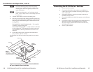
A typical IR 102 Kit application
The IR 102 Remote Receiver connects via cable to the switcher’s
rear panel RS-232 connector, and it uses the switcher’s RS-232
interface for input selection. The Remote Receiver also has an
RS-232 input connector, to permit the switcher to be controlled
by a PC or control system, even when the switcher’s RS-232 port
is occupied by the IR 102 Remote Receiver.
N
The remote control can operate a switcher only if the
switcher is configured as master, with no switchers
slaved to it. Refer to the switcher’s manual for
information on switcher configuration.