


IR 102 Remote Control Kit • Installation and Operation
Installation and Operation, cont’d
1-6
IR 102 Remote Control Kit • Installation and Operation
1-7
N
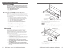
On the side mounting plates, devices are typically
mounted on the outside of the bracket. On the front
mounting plate, devices are typically mounted on the
inside of the bracket.
N
The front mounting plate is 1/4" taller than the side
plates. This size helps ensure the accessibility of buttons
or connectors.
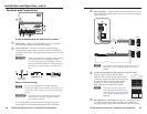
3. Affix the black rubber pad to the mounting plate.
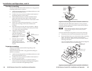
4. Place the U-bolt around the ceiling pole and insert the two
legs of the U-bolt through the slotted holes on the bracket’s
mounting plate and then through the slotted holes on the
backing brace.
For a typical (1.5" to 2.0" diameter) pole — The supplied
U-bolt fits a typical ceiling pole.
For a smaller or larger pole — Locally obtain a U-bolt that
fits the ceiling pole. The slotted holes on the bracket will
accommodate a U-bolt for pole sizes from 1.0" to 2.5" in
diameter.
5. Secure the bracket to the U-bolt with the included hex
nuts, washers, and lock washers.
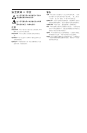
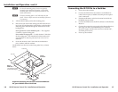
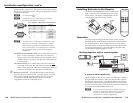
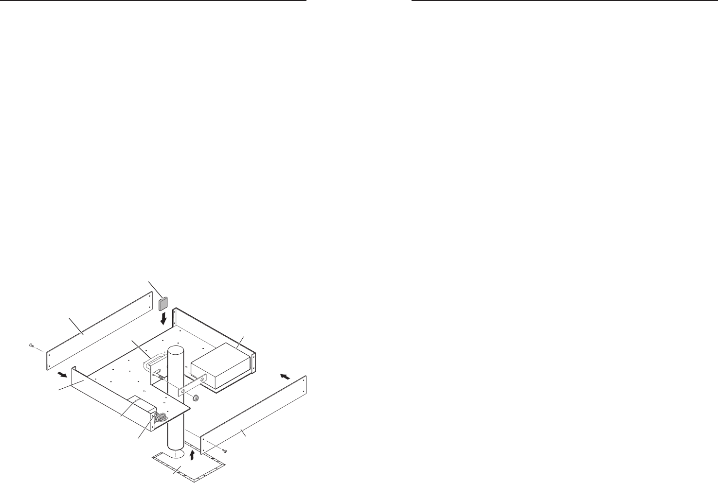
The IR 102 Rx can also be mounted using other kits, as shown
below.
Extron
PMK 350
Low Profile Two-product
Projector Mounting Kit
Extron
Power Supply
Plastic Tie
Extron
IR 102 Rx
Cover Sheet
Front Plate
Rear Plate
Rubber Pad
U-bolt
Projector mounting the IR 102 Rx with the PMK 350
kit, part #70-563-02 or #70-563-03
Connecting the IR 102 Rx to a Switcher
1. Power down the switcher.
2. Connect the IR 102 Rx to the switcher via the RS-232 or
contact closure ports, available on both 9-pin and captive
screw connectors.
3. Position the IR sensor at the best location for the IR 102
handheld remote control.
4. Connect the IR Sensor to the IR In connector on the Remote
Receiver.
5. Connect the external power supply to the Remote Receiver,
then plug one end of a standard IEC power cord into
the power supply and the other end into a 100-240 VAC,
50/60 Hz power source.
6. Power up the switcher.