


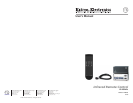

IR 102 Remote Control Kit • Installation and Operation
Installation and Operation, cont’d
1-8
IR 102 Remote Control Kit • Installation and Operation
1-9
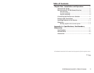
Features and Connections
IR 102 Rx UNIVERSAL IR REMOTE RECEIVER
RS-232/
CONTACT
OUT
RS-232
Tx Rx1 2 3 4 5+5
+12V
6
CONTROL OUT
IR IN
CONTACT
MOD
DEMOD
POWER
12V
.5A MAX
RS-232
IN
4
1
2
3
6
5
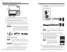
IR 102 Rx Remote Receiver front and rear panels
a
Power LED — When lit, this LED indicates power is applied.
The LED blinks during communication activity.
b
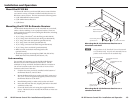
Power connector — Plug the external 12 V power supply
into this 2-pole captive screw connector. The power supply is
included with the unit. The figure below shows how to wire the
connector.
C
When connecting the power supply, voltage polarity
is extremely important. Applying power with
incorrect voltage polarity could damage the power
supply and the Remote Receiver. Identify the power
cord negative lead by the ridges on the side of the
cord.
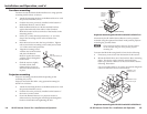
Power Supply
Output Cord
Captive Screw
Connector
Power Wiring.eps
A A
SECTION A–A
Power connector wiring
N
Do not tin the stripped power supply leads before
installing the captive screw connector. Tinned wires are
not as secure in the captive screw connectors and could
pull out.
W
The two power cord wires must be kept separate
while the power supply is plugged in. Remove
power before continuing.
To verify the polarity before connection, plug in the power
supply with no load and check the output with a voltmeter.
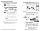
c
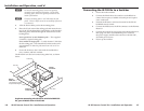
IR In connector — Plug the cable from the IR sensor or from an
Extron IR Link infrared repeater into this 3.5 mm, 5-pole captive
screw connector.
Modulated IR
+12VDC
21' max.
Ground ( )
Ground ( )
IR In connector wiring_030606.eps
IR In
MOD
DEMOD
+12V
+5V
or
IR In
MOD
DEMOD
+12V
+5V
IR
Sensor
IR Link
N
The maximum cable length for the IR sensor is 21 feet
(6.4 meters). Cut or extend the IR sensor’s cable as
needed.
d
Contact / RS-232 (Control Out) connector (captive screw) —
Plug the contact closure/RS-232 output
cable into this 3.5 mm, 10-pole captive screw
connector, and plug the other end of the cable
into the switcher’s contact closure/RS-232
control port. This permits the IR 102 Rx
Remote Receiver to control the switcher.
N
The IR 102 Kit can be used with
an Extron MPS 112 switcher only
when the switcher is in single switch
mode. Refer to the MPS 112 User’s
Manual.
e
RS-232/Contact – Out connector (9-pin D) — Plug the RS-232
or contact closure output cable into this 9-pin D connector,
and plug the other end of the cable into the switcher’s contact
1 Tx Rx2 3 4 5 6
RS-232
CONTROL OUT
CONTACT
Pin - 1
Pin - 2
Pin - 3
Pin - 4
Pin - 5
Pin - 6
Gnd
Tx
Rx
Gnd
Contact Closure
RS-232