


RGB 460
xixi
xixi
xi Series • Installation and Operation
RGB 460
xixi
xixi
xi Series • Installation and Operation
Installation and Operation, cont’d
2-10 2-11
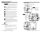
If the LED does not light, check the wiring at both the interface
and the power supply, and ensure that the power supply is
connected to a power source.
If the input signal has sync on green, the LED will not
change from yellow to green.
If the image does not appear or there is no sound
1. Make sure that all the devices are powered on.
2. Ensure that the connectors are wired correctly at both ends
of the cables. Audio cables must be wired for an
unbalanced stereo input signal and for a balanced or an
unbalanced stereo output signal.
3. If input is from a laptop computer and no picture appears,
use a laptop breakout cable for the input connection.
Check the computer’s user’s guide or contact Extron to
determine if special commands are required to output
video to the external video port. Also, many laptops’
screens shut off after the external video port is activated.
4. Call the Extron S
3
Sales and Technical Support Hotline if
the image still does not appear or there is no sound.
If the image is not displayed correctly
1. If the picture is too bright or dark, or if the edges of the
image seem to exceed their boundaries, or if thin lines and
sharp edges look thick and fuzzy, change the gain setting.
2. If the picture appears and is stable, but it has ghosting or
blooming, verify that the video input is properly
terminated. If the problem is not resolved by changing the
termination, try using a different input cable. Poor quality
or damaged cable can cause ghosting or blooming.
3. If the picture still is not displayed correctly, call the Extron
S
3
Sales and Technical Support Hotline.
If the interface does not respond to horizontal shifting
1. If the picture does not move on screen when the horizontal
shift control knob is rotated, DDSP is in use. Set the DDSP
DIP switch to Off.
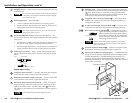
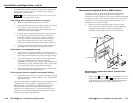
Once the system has been cabled and tested, the interface can be
installed in the wall or furniture. If optional AAP devices
(RGB 468xi only), or MAAP devices (RGB 468 Mxi only), are
being installed, see the following section “Mounting the
optional AAP or MAAP device”. To mount the interface to a
wall box, refer to the RGB 400xi Series installation guide that
addresses your specific requirements.
Mounting the optional AAP or MAAP device
The interface and any optional architectural adapter plates
(standard or mini) must be cabled before the interface is
installed in a wall or furniture. The screws needed for installing
the optional standard AAP devices are built into its front panel,
and hex screws are provided with the MAAP devices, so no
additional screws will be needed.
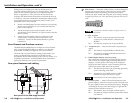
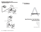
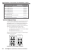
1. Before any cables are attached to the front of an AAP
device, secure the optional AAP devices to the faceplate
with the provided captive washers and #4-40 nuts
(standard AAPs), or the 3/32” hex screws (MAAPs).
Mounting the optional AAP device (standard AAP
device shown)
2. Follow steps
3
through
9
in the “Installation Overview”
section of this chapter. For step
8
(mounting the interface
to the wall box), refer to the RGB 400xi Series installation
guide that addresses your specific requirements.
#4-40 Nut w/ Captive
Washer
4-gang Wall Box
H
. SH
IF
T
M
IN
/M
A
X
T
M
RGB 468
I
N
P
U
T
M
O
N
IT
O
R
AUDIO
R
G
B
4
6
8
W
IT
H
A
D
S
P
M
O
N
IT
O
R
N
O
M
O
N
IT
O
R