


RGB 460
xixi
xixi
xi Series • Installation and Operation
RGB 460
xixi
xixi
xi Series • Installation and Operation
Installation and Operation, cont’d
2-6 2-7
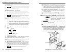
Blank plates (two single-space and one double-space) are
included with the interfaces to cover unused spaces. Adapter
plates must be ordered separately (see “Optional Adapter
Plates” in appendix A). They must also be attached to the
faceplate and cabled before the interface is installed in the wall
or furniture. The screws needed for installing the adapter plates
are supplied (MAAPs), or built into the plates (AAPs), so no
additional screws will be needed.
1. Remove the blank plates from the interface by unscrewing
the hex screws (MAAPs), or nuts (AAPs) that fasten the
plates to the faceplate.
2. Attach the adapter plates to the faceplate with the
provided hex screws (MAAPs), or captive washers and #4-
40 nuts (AAPs).
3. Attach the output cables to the rear connectors of the
adapter plates. Soldering will be required for some
connectors. Attach foil and braided shields to ground
connections.
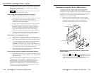
Euro Channel and floorbox versions
The RGB 460xi and RGB 468xi are available in a Euro Channel
(EC) version and the RGB 460xi is available in two floorbox
models (MK and FSR) (see appendix A for part numbers).
The front and rear panel features, cabling requirements, and
testing/troubleshooting procedures are identical to the
descriptions shown in this chapter for the wall box models. For
installation instructions, see the RGB 400xi Series installation
guide that addresses your specific requirements.
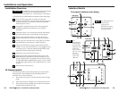
Rear panel features and cabling
Rear panel of the RGB 464
xixi
xixi
xi
interface
1
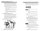
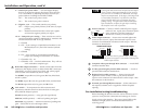
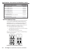
DIP switches — This bank of DIP switches, as illustrated below,
controls sync on green output, composite sync output, DDSP
(Digital Display Sync Processing), serration pulse output,
vertical sync pulse width, and composite sync routing. Moving
a switch up will set it to “On” and moving it down will set it to
“Off”.
3
4
5
6
1
2
7
8
Closed / On
Open / Off
The default for all DIP switches except for switch 7 is
Off (down).
1 — Sync on green
Off — The interface outputs separate horizontal and
vertical sync (on the H and V connectors) for
RGBHV.
On — The interface outputs sync on green (RGsB).
2 — Composite sync — This switch controls composite sync
output.
Off — The interface outputs RGBHV or RGsB video.
On — The interface outputs combined horizontal and
vertical sync for RGBS.
3 — DDSP (Digital Display Sync Processing)
This feature may be necessary for digital display devices
such as LCD, DLP (digital light processing) and plasma
displays. Use this option if the image is not displayed
properly after other options, such as serration pulse and
vertical sync pulse width, have been explored.
Off — The interface performs sync processing operations,
such as centering, with ADSP.
On — The interface uses DDSP instead of ADSP.
DDSP does not process the sync signal.
DDSP disables the horizontal shifting control.
4 — Serration pulse — Many LCD and DLP projectors and
plasma displays, must have serration pulses removed from
the sync signal in order to be displayed properly. Flagging
or bending at the top of the video image is a sign that the
serration pulses should be removed.
Off — The interface does not output serration pulses.
On — The interface outputs serration pulses in the vertical
sync interval.
4
8
5
3
7
6
2
9
4
8
5
3
7
6
2
9
51