


RGB 460
xixi
xixi
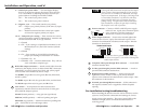
xi Series • Installation and Operation
RGB 460
xixi
xixi
xi Series • Installation and Operation
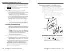
Installation and Operation, cont’d
2-8 2-9
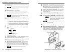
If the signal cable between the interface and the output
device is shorter than approximately 125 feet, and the
gain switch is set to Medium or Maximum, the image
may be overcompensated. If the edges of the image seem
to exceed their boundaries, or if thin lines and sharp
edges look thick and fuzzy, try changing the gain/
peaking setting. The gain switch will be inaccessible
after installation, so adjust the gain before installing
the interface into a wall or furniture.
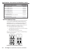
4
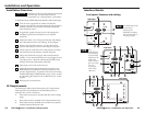
Power connector — Connect a 9VDC to 24VDC power supply
to this 3.5 mm, 2-pole, direct insertion captive
screw connector. Wire the connector as
shown here. Polarity is not important.
5
Audio output connector — Insert wires into and tighten the
screws on this 3.5 mm, 5-pole, direct insertion captive screw
connector for unbalanced or balanced audio output. Wire the
connector as shown here.
CAUTION
Connect the sleeve to ground (Gnd). Connecting
the sleeve to a negative (-) terminal will damage the
audio output circuits.
6
Composite video pass-through RCA connector — A male BNC
connector attaches here.
7
S-video pass-through 4-pin mini DIN connector — A male 4-
pin mini DIN connector attaches here.
8
Balanced active audio connector — Insert wires into and
tighten the screws on this 3.5 mm, 5-pole, direct insertion
captive screw connector for balanced active audio output. Wire
the connector as shown above.
9
Network pass-through RJ-45 connector — If this connector is
not required, a blank cover is supplied to fill this faceplate
opening.
Pre-installation testing/troubleshooting
Before installing the interface into the wall or furniture, test the
system to verify that the connections and settings are correct.
Apply power to the interface. The power/signal LED on the
interface will light yellow to indicate that the interface is
receiving power.
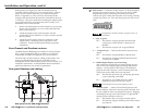
5 — Vertical sync pulse width — For some digital display
devices, if no picture appears, the picture cuts in and out,
or it is scrambled, try adjusting the output vertical sync
pulse width or switching from ADSP to DDSP.
Off — The vertical sync pulse is wide.
On — The vertical sync pulse is narrow.
6 — Negative sync — This switch controls sync polarity.
Off — Output sync polarity follows (is the same as) input
polarity.
On — Both the horizontal and the vertical sync signals
are forced to negative polarity on output.
7 & 8 — Composite sync routing — These switches are used to
route local monitor signals for Macintosh 13” monitors and
all other Macintosh and VGA-type monitors.
7 = On and
8 = Off — Sync routing to 15-pin HD local monitor for all
Macintosh (non-13”) and VGA monitors (default
setting).
7 = Off and
8 = On — Sync routing to 15-pin HD local monitor for
proper sync routing to a Macintosh 13” monitor.
7 = On and 8 = On or
7 = Off and 8 = Off — Invalid combinations. They will not
work with either computer type.
2
RGB video output connectors — Attach coaxial cables from the
interface to the display device via these female BNC connectors.
These BNCs are on red, green, blue, black, and yellow pigtail
wires secured to the interface by the tie wraps.
For RGBHV output: R is red, G is green, B is blue, H is black,
and V is yellow.
For RGBS output: R is red, G is green, B is blue, and S is black.
For RGsB output: R is red, G is green, and B is blue.
3
Gain switch — To compensate for cable resistance and
capacitance, slide this switch to select the level of video gain
that yields the sharpest picture.
Normal (bottom position) — unity gain (no signal boost)
Medium (middle position) — mid-level peaking and gain
Maximum (top position) — maximum amount of peaking and
gain — Select this for use with longer cables.
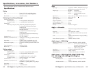
Balanced Output
Ring
Tip
Sleeve (s)
Ring
Tip
L
+
L
-
R
+
R
-
Audio
Unbalanced Output
Tip
See Caution
Sleeve (s)
Tip
See Caution
L
+
L
-
R
+
R
-
Audio
+ or –
– or +
9-24VDC
Power