


1750
Operators Manual
6
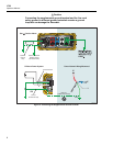
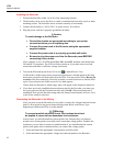
Table 3. Input Terminals and Controls
Number Description
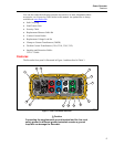
A Standard 120/240 V 50/60 Hz power input for Recorder power
B Voltage indicator
Steady Voltage is present, not overloaded
Blinking Voltage overload (overload threshold 1100 V)
C Five voltage measurement inputs
D Removable Secure Digital (SD) memory card for transfer of large quantities of data. You can
remove the card from the Recorder, insert in the PDA and transfer data to the PC via the
“synchronize data” feature of the PDA. A USB SD card reader may also be used.
E SD status indicator
Steady green SD card inserted
Blinking Busy - do not remove the card
F Wireless Controller Status Indicator
Steady Blue Wireless controller enabled but not communicating
Blinking Wireless controller communicating
Off Inactive
G Ethernet port. TCP/IP via Ethernet is used to connect the Recorder to a PC for downloading
recorded data, and for configuring the Recorder when not using the PDA. This is the
recommended method of data transfer due to its speed and reliability.
H Busy Indicator
Blinking Network is busy
I Link indicator
Off No link
Steady Link Present
Blinking Communicating with PC
J Current Measurement Terminals (5)
K Current indicator
Steady Current probe in normal range
Blinking > 110% of probe range, use a higher range probe
Off Current insufficient to measure
L Power LED
Steady green AC input power normal, instrument is not booted or locked
Green/Orange blinking Recording
Blinking red Recorder running on UPS
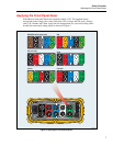
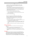
M Ground Terminal
Connecting the supplemental ground terminal and the line cord safety ground to different
ground potentials creates a ground loop that can damage the Recorder. To avoid this, use the
supplemental ground terminal only when no protective earth ground connection exists through
the line power cord. If there is any chance that a safety ground connection does exist through
the line power cord connection, make sure to connect the supplemental ground terminal only to
the ground system used by the ac receptacle that powers the Recorder. See Figure 3.