


1750
Operators Manual
14
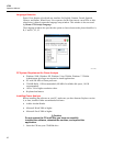
descriptions such as company, name, and measurement purpose. This can be done at this
point or after downloading the measurement data.
Managing Recorded Data
Recorded data resides in the Recorder on an internal non-physically accessible flash
memory circuit. It is not transferred to an SD memory card in the Recorder’s SD memory
slot until you request a download action using the PDA or an attached PC. Downloading
to a PC running Fluke Power Analyze Software (included) using the Ethernet cable is
recommended and the fastest way to retrieve data from the Recorder.
It is never technically necessary to erase internal memory. When the Recorder has new
data to record, it does so automatically, overwriting the oldest data (circular memory).
You can erase internal memory for security reasons, or if you want to simplify what you
will be seeing in the download data screen. The start and end times will represent one
recording session when old data is erased.
Note
Data is not removed from internal Recorder memory until you erase it
using Power View software on the PDA or Power Analyze software on your
PC.
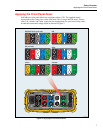
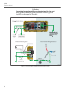
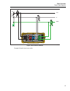
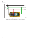
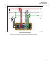
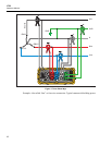
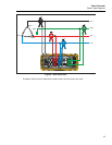
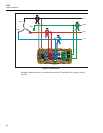
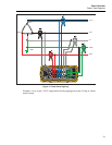
Power Type Diagrams
The wiring illustrations included cover the standard power configurations that are
selectable in Power View or Power Analyze software. The diagrams are provided as an
aid in making the correct test lead connections. Power type diagrams are also included on
your PDA and can be referenced when you are setting up nominal power on the Recorder.
Available power type settings are:
• One-Phase Plus Neutral (Figure 4)
• One-Phase IT No Neutral (Figure 5)
• One-Phase-Split Phase (Figure 6)
• Three-Phase Wye (Figure 7)
• Three-Phase Delta (Figure 8)
• Three-Phase IT (Figure 9)
• Three-Phase High Leg (Figure 10)
• Three-Phase Open Leg (Figure 11)
• 2-Element Delta (Figure 12)
• 2 ½-Element Wye (Figure 13)