80 Series V
Calibration Manual
6
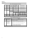
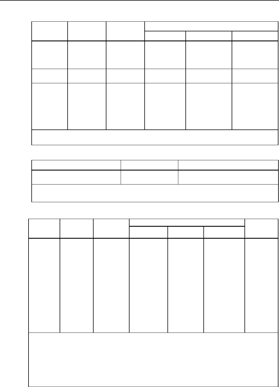
Table 4. DC Voltage, Resistance, and Conductance Function Specifications
Accuracy
Function Range Resolution
Model 83 Model 87 Model 88
L
6.000 V
60.00 V
600.0 V
1000 V
0.001 V
0.01 V
0.1 V
1 V
± (0.1 % + 1)
± (0.1 % + 1)
± (0.1 % + 1)
± (0.1 % + 1)
± (0.05 % + 1)
± (0.05 % + 1)
± (0.05 % + 1)
± (0.05 % + 1)
± (0.1 % + 1)
± (0.1 % + 1)
± (0.1 % + 1)
± (0.1 % + 1)
F
mV
600.0 mV 0.1 mV ± (0.3 % + 1) ± (0.1 % + 1) ± (0.3 % + 1)
e
nS
600.0 Ω
6.000 kΩ
60.00 kΩ
600.0 kΩ
6.000 MΩ
50.00 MΩ
60.00 nS
0.1 Ω
0.001 kΩ
0.01 kΩ
0.1 kΩ
0.001 MΩ
0.01 MΩ
0.01 nS
± (0.4 % + 2)
1
± (0.4 % + 1)
± (0.4 % + 1)
± (0.7 % + 1)
± (0.7 % + 1)
± (1.0 % + 3)
2
± (1.0 % + 10)
1
± (0.2 % + 2)
1
± (0.2 % + 1)
± (0.2 % + 1)
± (0.6 % + 1)
± (0.6 % + 1)
± (1.0 % + 3)
2
± (1.0 % + 10)
1
± (0.4 % + 2)
1
± (0.4 % + 1)
± (0.4 % + 1)
± (0.7 % + 1)
± (0.7 % + 1)
± (1.0 % + 3)
2
± (1.0 % + 10)
1
1. When using the REL ∆ function to compensate for offsets.
2. Add 0.5 % of reading when measuring above 30 MΩ in the 50 MΩ range, and 20 counts below 33 nS in the 60
nS range.
Table 5. Temperature Specifications (87 and 88 Only)
Temperature Resolution Accuracy
1,2
-200 °C to +1090 °C
-328 °F to +1994 °F
0.1 °C
0.1 °F
1 % + 10
1 % + 18
1. Does not include error of the thermocouple probe.
2. Accuracy specification assumes ambient temperature stable to
± 1 °C. For ambient temperature changes of ± 5 °C,
rated accuracy applies after 1 hour.
Table 6. Current Function Specifications
Accuracy
Function Range Resolution
Model 83
1
Model 87
2, 3
Model 88
1
Burden
Voltage
(typical)
mA
\
(45 Hz to
2 kHz)
mA
[
60.00 mA
400.0 mA
6
6.000 A
10.00 A
4
60.00 mA
400.0 mA
6
6.000 A
10.00 A
4
0.01 mA
0.1 mA
0.001 A
0.01 A
0.01 mA
0.1 mA
0.001 A
0.01 A
± (1.2 % + 2)
5
± (1.2 % + 2)
5
± (1.2 % + 2)
5
± (1.2 % + 2)
5
± (0.4 % + 4)
± (0.4 % + 2)
± (0.4 % + 4)
± (0.4 % + 2)
± (1.0 % + 2)
± (1.0 % + 2)
± (1.0 % + 2)
± (1.0 % + 2)
± (0.2 % + 4)
± (0.2 % + 2)
± (0.2 % + 4)
± (0.2 % + 2)
± (1.2 % + 2)
5
± (1.2 % + 2)
5
± (1.2 % + 2)
5
± (1.2 % + 2)
5
± (0.4 % + 4)
± (0.4 % + 2)
± (0.4 % + 4)
± (0.4 % + 2)
1.8 mV/mA
1.8 mV/mA
0.03 V/A
0.03 V/A
1.8 mV/mA
1.8 mV/mA
0.03 V/A
0.03 V/A
µA B
(45 Hz to
2 kHz)
µAF
600.0 µA
6000 µA
600.0 µA
6000 µA
0.1 µA
1 µA
0.1 µA
1 µA
± (1.2 % + 2)
5
± (1.2 % + 2)
5
± (0.4 % + 4)
± (0.4 % + 2)
± (1.0 % + 2)
± (1.0 % + 2)
± (0.2 % + 4)
± (0.2 % + 2)
± (1.2 % + 2)
5
± (1.2 % + 2)
5
± (0.4 % + 4)
± (0.4 % + 2)
100 µV/µA
100 µV/µA
100 µV/µA
100 µV/µA
1. AC conversion for Model 83 and 88 is ac coupled and calibrated to the rms value of a sine wave input.
2. AC conversions for Model 87 are ac coupled, true rms responding, and valid from 3 % to 100 % of range, except
400 mA range (5 % to 100 % of range) and 10 A range (15 % to 100 % or range).
3. Model 87 is a true rms responding meter. When the input leads are shorted together in the ac functions, the Meter
may display a residual reading between 1 and 30 counts. A 30 count residual reading will cause only a 2 digit
change for readings over 3 % of range. Using REL to offset this reading may produce a much larger constant
error in later measurements
4. W 10 A continuous up to 35 °C; < 20 minutes on, 5 minutes off at 35 °C to 55 °C. 20 A for 30 seconds maximum;
> 10 A unspecified.
5. Below a reading of 200 counts, add 10 counts.
6. 400 mA continuous; 600 mA for 18 hrs maximum.


