


18
Model D2424LV Quick Operation Guide
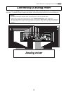
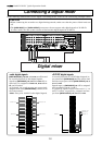
In the following, basic multi-recording of adat digital signals will be carried out on the assumption that a
digital mixer is connected to D2424LV (To output adat digital signals from the digital mixer, refer to the
Operating Manual of the digital mixer you are using). Prior to operation, D2424LV must be set to the “Initial
state.”
Basic digital recording
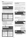
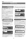
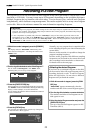
1. Press the [SETUP] key to enter the SETUP mode.
2. Select the “D. in?” menu by using the Jog dial,
and press the [EXECUTE/YES] key.
The current selection will be displayed together with
"D. in?" (the default is "Analog").
By pressing the [EXECUTE/YES] key, the selection starts
flashing, showing that you can now change the
selection.
Selecting Digital In
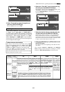
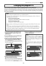
3. Select “adat: Async” or “adat: Sync” by using the
Jog dial, and press the [EXECUTE/YES] key.
To lock the mixing console to recorder's WORD OUT (or
digital out), select “adat: Async”.
If the mixing console cannot be locked to the digital word
clock, select “adat: Sync”.
Flashing
Flashing
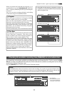
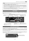
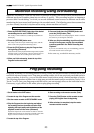
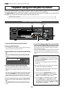
Selecting Digital Out
After completing the Digital In setting, select "Digital Out".
When setting Digital In to an "Async" mode (“adat: Async”
or “SPDIF: Async”), Also select "Reference clock".
4. Select the “D.out?” menu by using the Jog dial,
and press the [EXECUTE/YES] key.
The current selection is displayed together with "D. out?".
The default is “D.out adat”. If another selection is
displayed,select “D.out adat” using the following
operation. Press the [EXECUTE/YES] key and the
current selection will starts flashing.
<About Digital Out selection>
In addition to the initial setting of "D.out adat" from
among the digital out setup items, "D.out SPDIF" can
also be selected, and setup in compliance with the ap-
plication. When set to "D.out adat," outputs of tracks 1
-8 (6-16, 17-24) will be assigned to digital out. This will
be the initial setting and signals can be output to digi-
tal mixers and adat equipments provided with adat in-
put functions. The following signals will be output from
each [DATA OUTPUT] connectors.
[DATA OUTPUT] 1-8: Outputs of tracks 1 - 8
[DATA OUTPUT] 9-16: Ouputs of tracks 9 - 16
[DATA OUTPUT] 17-24: Outputs of tracks 17 - 24
When set to "D.out SPDIF," outputs of two tracks (1-2,
3-4, 5-6) will be assigned to digital out. It will thus be
possible to ouput S/P DIF signals (L, R) to external digi-
tal equipments. Signals listed below will be output from
each [DATA OUTPUT] connectors.
[DATA OUTPUT] 1-8: Outputs of tracks 1 - 2
[DATA OUTPUT] 9-16: Outputs of tracks 3 - 4
[DATA OUTPUT] 17-24: Outputs of tracks 5 - 6
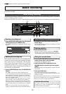
<About Digital In selection>
For setup items of digital in, in addition to the initial
setting of "Analog," "SPDIF: Async," "SPDIF: Sync," "adat:
Async" or "adat: Sync" can be selected and setup to match
the application.
"Analog" indicates that none of the tracks are assigned
to digital in and is the setting in which digital signals
cannot be input to any of the [DATA INPUT] connectors.
"SPDIF:Async" and "SPDIF: Sync" are used when assign-
ing S/P DIF signals (L, R) from external digital equip-
ment to tracks 1 and 2 of D2424LV, and selected to
digital in asynchronous (Async) or synchronous (Sync)
depending on the system in
use. In this case, [DATA INPUT] 1-8 only can be used.
"adat:Async" and "adat: Sync" are used to assign adat
signals (ch 1-ch 8) from external digital equipments to
tracks 1-8 (9-16, 17-24) of D2424LV, and in compli-
ance to the system, select it to asynchronous (Async)
or synchronous (Sync) with digital-in.
In this case, all [DATA INPUT] connctors can be used and
each input port will function as shown below.
[DATA INPUT] 1-8: Tracks 1 - 8 will be assigned.
[DATA INPUT] 9-16: Tracks 9 - 16 will be assigned.
[DATA INPUT] 17-24: Tracks 17 - 24 will be assigned.
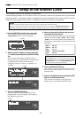
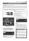
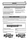
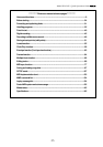
"DIGITAL" will be lit if set to the asynchronous mode while
a correct adat digital signal is being input from the digital
mixer, and "EXT" will also be lit if set to the synchronous
mode. If it is locked to the word signal, "WORD" will be lit.
∞
42
OL
0
30
24
18
12
9
6
3
kHz
24
FS
BIT
SETUP
24
∞
42
OL
0
30
24
18
12
9
6
3
2322
21
20
19
18
17
1615141312
11
10
98765
4
3
2
1
CLOCK
∞
42
OL
0
30
24
18
12
9
6
3
kHz
24
FS
BIT
SETUP
24
∞
42
OL
0
30
24
18
12
9
6
3
2322
21
20
19
18
17
1615141312
11
10
98765
4
3
2
1
CLOCK
∞
42
OL
0
30
24
18
12
9
6
3
kHz
24
FS
BIT
SETUP
24
∞
42
OL
0
30
24
18
12
9
6
3
2322
21
20
19
18
17
1615141312
11
10
98765
4
3
2
1
EXT
CLOCK
DIGITAL
WORD
∞
42
OL
0
30
24
18
12
9
6
3
kHz
24
FS
BIT
SETUP
24
∞
42
OL
0
30
24
18
12
9
6
3
2322
21
20
19
18
17
1615141312
11
10
98765
4
3
2
1
CLOCK