


Chapter 1 System Overview 1-19
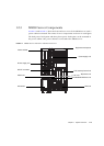
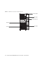
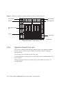
Operator Panel Appearance
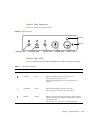
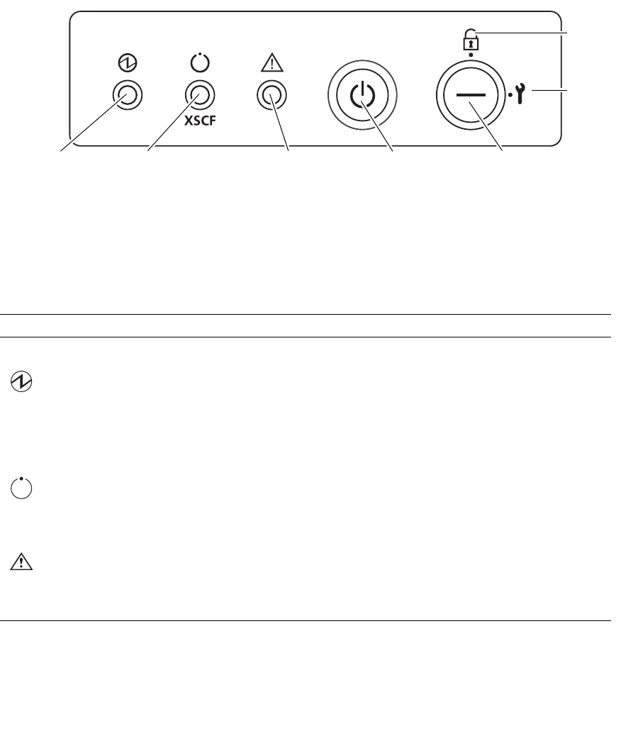
FIGURE 1-10 shows the operator panel.
FIGURE 1-10 Operator Panel
Operator Panel LEDs
TABLE 1-4 lists the operating states indicated by the LEDs on the operator panel.
TABLE 1-4 Operator Panel LEDs
LEDs Name Light color Description of function and operating state
POWER Green Indicates whether the main unit power is on.
If this LED is on, the power is on.
If this LED is blinking, the power-off sequence is in
progress.
STANDBY Green Indicates the standby state of the main unit.
If this LED is on, the power can be turned on.
CHECK Amber Indicates the main unit operating status. (This is used to
indicate a maintenance target, or it indicates that the unit
cannot be started.)
If this LED is on, a system error has been detected.
Locked
Service
MODE switch
POWER switchCHECK (LED)STANDBY (LED)
POWER (LED)