


6
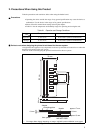
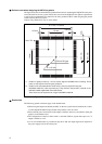
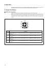
■ Points to note when designing the MCU foot pattern
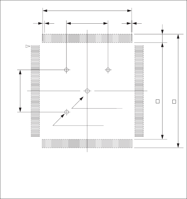
The figure shows the recommended foot pattern dimensions for mounting the NQPACK on the print-
ed circuit board for the user system. Please take account of the NQPACK foot pattern requirements
as well as the recommended foot pattern for the mass production MCU when designing the printed
circuit board for the user system.
Contact Tokyo Eletech Co. Ltd. for more details.
Figure 2.2 Foot Pattern Dimensions for Mounting the NQPACK
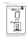
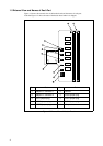
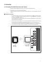
■ Restrictions
The following general restrictions apply to the header board.
• When using the adapter and header, the MCU on the user system must be mounted in a socket.
Use the NQPACK176SD (Tokyo Eletech Corporation) as the IC socket.
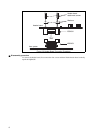
• Ensure that all power is turned off to the adapter, emulator, and user system before setting the
jumpers on the header board.
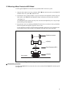
• The configuration of the level shift circuit is such that VOH for signals that expect a 4.5 V
output is limited to 4.4 V.
• As no level shift function is provided for pins 89 to 108, the output signal level depends on
the power supply used to drive these pins.
*1 : Position of guide pin holes (φ 1.0 mm) used to align the NQPACK when mounting. These
holes are not required if not using the guide pins.
*2 : Position of IC socket attachment screw holes (φ 3.2 mm) required if using the
NQPACK176SD-SL (sold separately by Tokyo Eletech Corporation) instead of the
NQPACK176SD supplied with the header board.
These holes are not required if not using the NQPACK176SD-SL.
0.5 × 43 = 21.5 mm
0.5 mm
10 mm
0.25 mm
2 mm
23.1 mm
27.1 mm
φ 3.2 mm SL-type
3- φ 1.0 mm
10 mm
No.1 Pin