


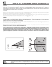
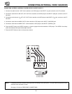
REAR SPEAKER TERMINAL CONNECTIONS
12
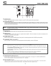
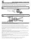
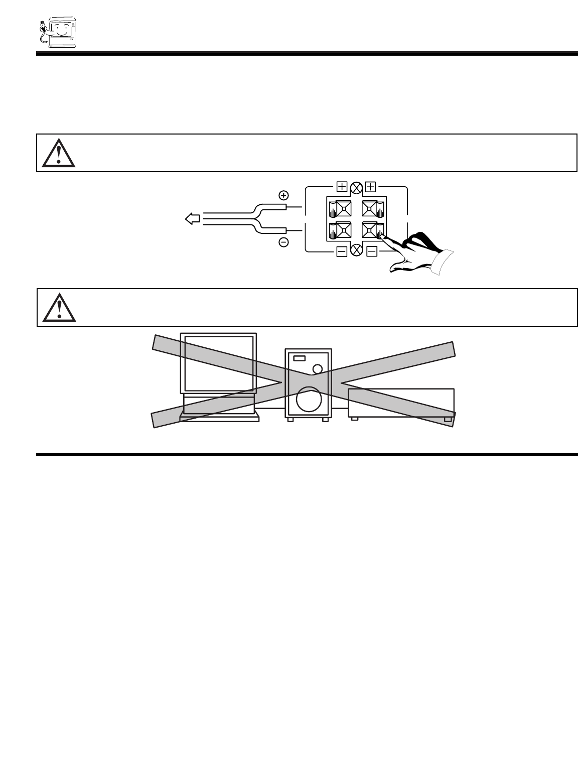
CONNECT AFTER TURNING THE POWER OF THE TV OFF.
Press the Right Speaker red button and insert the positive (+) lead wire into the hole next to the button. Once the wire is
in place, pull the red button back to original position and the wire is locked into place. In the same manner, press the
Right Speaker black button and insert the negative (-) lead wire. Repeat this procedure for the Left Speaker.
CAUTION: Do not short speaker terminals, (do not connect a wire directly across any two terminals). This could cause
damage to your audio outputs or other damage to your TV.
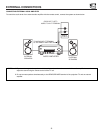
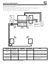
CAUTION: Do not connect speakers simultaneously to the REAR SPEAKER terminal of the Projection TV and an external
amplifier. This could damage both the TV and the speakers. Your TV was designed to use 8-Ohm speakers
only. Any other type may degrade the audio performance of your entertainment system.
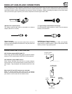
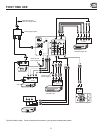
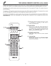
TIPS ON REAR PANEL CONNECTIONS
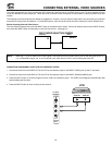
S-VIDEO connections are provided for high performance laserdisc players, VCRs etc. that have this feature. Use these connec-
tions in place of the standard video connection if your device has this feature.
If your device has only one audio output (mono sound), connect it to the left audio jack on the television.
Refer to the operating guide of your other electronic equipment for additional information on connecting your hook-up cables.
A single VCR can be used for VCR #1 and VCR #2, but note that a VCR cannot record its own video or line output (INPUT 1 in
the example on page 11.) Refer to your VCR operating guide for more information on line input-output connections.
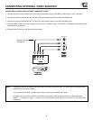
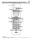
You may use VIDEO or COMPONENT VIDEO: Y-C
B
C
R
inputs to connect to INPUT 2, but note that only one of these may be
used at a time.
Connect only 1 component to each input jack.
COMPONENT VIDEO: Y-C
B
C
R
connections are provided for high performance components, such as DVD players. Use these
connections in place of the standard video connection if your device has this feature.
When using the Y-C
B
C
R
input jacks, connect your components audio output to the TV s INPUT 2 Left and Right Audio input
jacks.
Your component outputs may be labeled Y, B-Y, and R-Y. In this case, connect the components B-Y output to the TV s C
B
input
and the components R-Y output to the TV s C
R
input.
It may be necessary to adjust TINT or turn AUTO COLOR-ON to obtain optimum picture quality when using the Y-C
B
C
R
inputs.
(see pages 47 and 48)
To ensure no copyright infringement, the MONITOR OUT output will be abnormal, when using the Y-C
B
C
R
jacks.
When using the Y-C
B
C
R
jacks, INPUT 2 will be viewed as a blank PIP sub-picture. (see page 22)
TO
EXTERNAL
SPEAKER
R
L
Projection T.V.
Speaker
Amplifier