


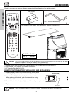
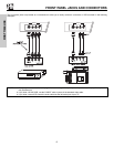

REAR PANEL JACKS
9
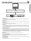
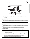
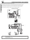
ቢ Antenna Input
ANT A
- A 75-Ohm RF antenna or CATV (Cable TV) input. ANT A can be displayed as a main picture or sub-picture.
ANT B- A 75-Ohm RF antenna input. ANT B can only be displayed as a main picture. ANT B cannot be displayed as a
sub-picture.
ባ Audio/Video Inputs 1, 2, 3 and 4
By using the INPUTS button, CURSOR buttons and SELECT button of the remote control you can select each video source. Use
the audio and video inputs to connect external devices, such as VCRs, camcorders, laserdisc players, DVD players etc. (If you have
mono sound, insert the audio cable into the left audio jack.)
ቤ MONIT
OR OUT
These jac
ks pro
vide fix
ed or v
ar
iab
le audio and video signals which are used f
or recording.
Use the S-VIDEO Output for high
quality video output (see page 63).
ብ S-VIDEO Inputs 3 and 4
Inputs 3 and 4 pro
vide S-V
IDEO
(Super
Video) jacks for connecting equipment with S-VIDEO output capability.
ቦ Component: Y-P
B
P
R
Inputs
Inputs 1 and 2 pro
vide
Y
-P
B
P
R
jac
ks f
or connecting equipment with this capability
, such as a DVD player or Set Top Box. You may
use composite video signal f
or both inputs
.
NOTE: You may use VIDEO or S-VIDEO inputs to connect to INPUT 3 and 4, but only one of these inputs may be used at a
time.
ቢ
ባ
ቤ
ብ
ቦ
ቧ
ቨ
ቩ
ቭ
ቪ
Apparatus Claims of U.S. Patent Nos.
4,631,603; 4,577,216; 4,819,098;
4,907,093; and 6,381,747 licensed
for limited viewing uses only.
1
2345
9
8
7
6
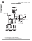
ቫ
ANT A
S-VIDEO
R
L
VIDEO
AUDIO
(MONO)
(MONO)
(MONO) (MONO)
P
R
P
B
Y/
VIDEO
Y/
VIDEO
P
R
P
B
MONITOR OUT INPUT 4 INPUT 3
INPUT 2 INPUT 1
HDMI 1
RS232C
ANT B
Upgrade Card
CableCARD
(Top of card faces right)
OPTICAL OUT
Digital Audio
AUDIO
TO HI-FI
TV AS CENTER
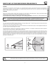
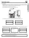
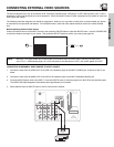
NOTE: You may ask your local cable company whether DTV services are available.
NO
TES:
1.
Do not connect composite
VIDEO and S-VIDEO to Input 3, 4 or 5 at the same time
. S-VIDEO has priority
o
v
er
VIDEO input.
2.
Your component outputs may be labeled Y, B-Y, and R-Y. In this case, connect the components B-Y output to the TV’s P
B
input and
the components R-Y output to the TV’s P
R
input.
3. Your component outputs may be labeled Y-C
B
C
R
. In this case, connect the component C
B
output to the TV’s P
B
input and the
component C
R
output to the TV’s P
R
input.
4. It may be necessary to adjust TINT to obtain optimum picture quality when using the Y-P
B
P
R
inputs (see page 37).
5. To ensure no copyright infringement, the MONITOR OUT output will be abnormal, when using the Y-P
B
P
R
jacks.
6. Input 1 and Input 2 (Y/VIDEO) can be used for composite video and component video input.
FIRST TIME USE