


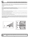
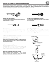
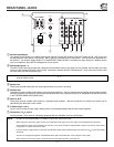
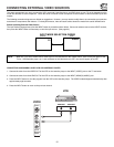
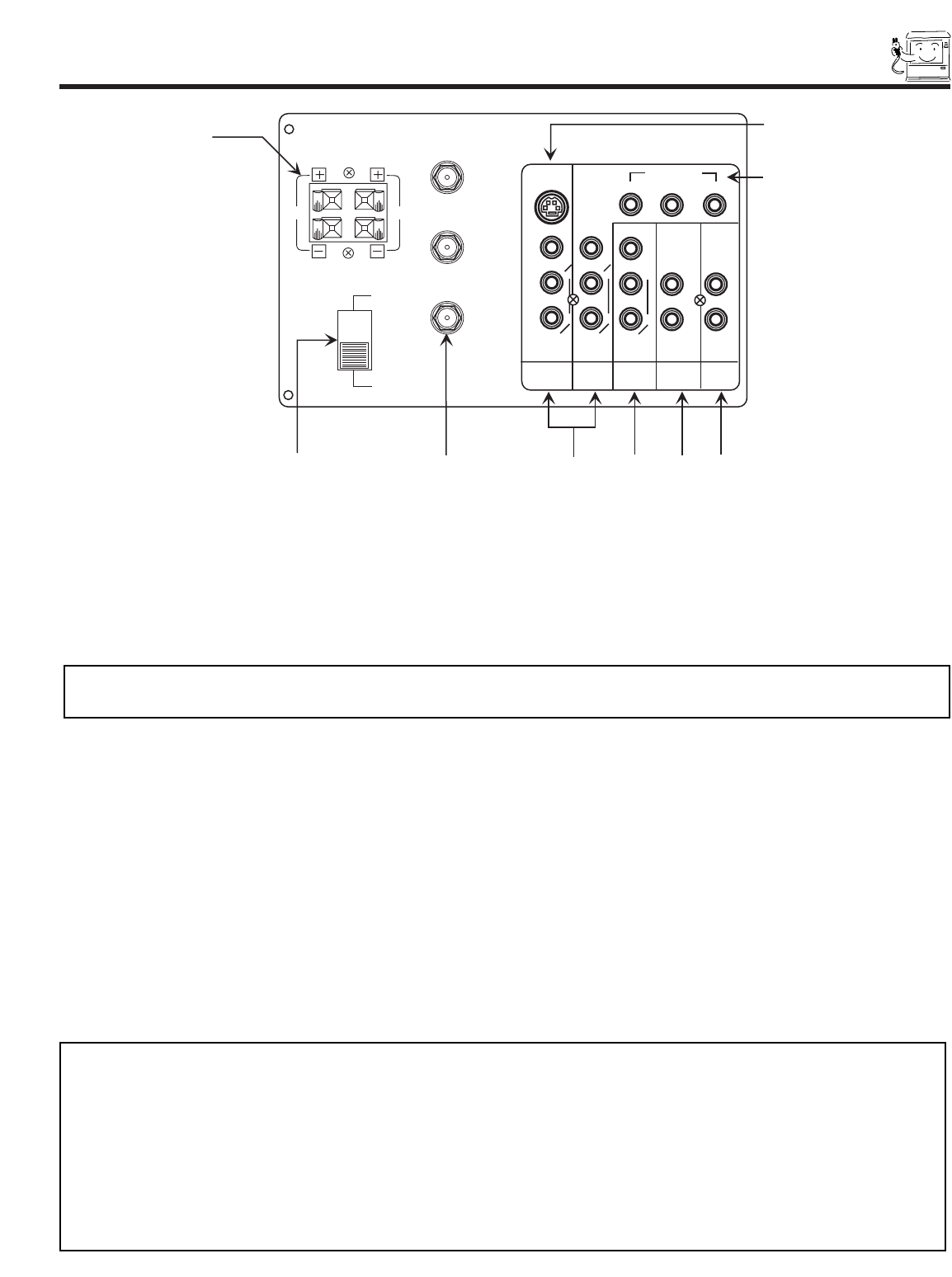
REAR PANEL JACKS
11
ቢ Antenna Input/Output
The remote control allows you to switch between two separate 75-Ohm RF antenna inputs, ANT A and ANT B. ANT A input can
be displayed as a main picture or sub-picture. ANT B can only be displayed as a main picture. (ANT B cannot be displayed as a
sub-picture.) The antenna output labeled “TO CONVERTER” allows the ANT A connection to pass directly to a different source
such as a cable box, when ANT B is displayed as a main picture.
ባ Audio/Video Inputs 1, 2
The INPUT button will step through each video source and antenna source input each time it is pressed. Use the audio and video
inputs to connect external devices, such as VCRs, camcorders, laserdisc players, DVD players etc. (If you have mono sound, insert
the audio cable into the left channel jack.)
ቤ Monitor Out
These jacks provide fixed audio and video signals which are used for recording.
ብ Wireless Out
These jacks provide variable audio output to a set of wireless speakers. They can also be used for another stereo system amplifier.
With this connection, the audio can be controlled by the television’s main volume and also by an independent volume feature found
in the THEATER-WIRELESS SOUND menu.
ቦ Audio to HI-FI
These jacks provide variable audio output to a separate stereo amplifier. With this connection, the audio to the stereo can be
controlled by the television’s main volume.
ᕈ S-Video Inputs 1 and 2
Inputs 1 and 2 provide S-Video (Super Video) jacks for connecting equipment with S-Video output capability.
ቨ Component: Y-C
b
C
r
Input 2
Input 2 provides Y-C
b
C
r
jacks for connecting equipment with this capability, such as a DVD player.
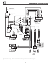
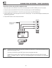
ᕄ
ᕅ
ᕆ
ᕇ
ᕈ
ᕉ
ቢ
RL
REAR SPEAKER
8Ω ONLY
SP. MATRIX
SURROUND
EXT.
ቩ
ቪ
WIRELESS
OUT
MONITOR
OUT
AUDIO
TO Hi-Fi
INPUT 2
INPUT 1
AUDIO
(MONO)
L
R
AUDIO
(MONO)
L
R
AUDIO
L
R
S-VIDEO
VIDEO
VIDEO
VIDEO
ANT A
TO
CONVERTER
ANT B
L
L
R
R
COMPONENT
Y Cb Cr
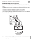
NOTE:
DO NOT connect standard VIDEO or S-VIDEO to Input 2 when using Y-C
b
C
r
input.
When using the Y-C
b
C
r
input jacks, connect your components audio output to the TV’s Input 2 Left and Right Audio input jacks.
Your component outputs may be labeled Y, B-Y, and R-Y. In this case, connect the components B-Y output to the TV’s Cb input and the
components R-Y output to the TV’s Cr input.
It may be nessary to adjust TINT or turn AUTO COLOR-ON to obtain optimum picture quality when using the Y-C
b
C
r
inputs. (See pages
49 and 50)
To ensure no copyright infringement, the MONITOR OUT output will be abnormal, when using the Y-C
b
C
r
jacks.
When using the Y-C
b
C
r
jacks, Input 2 will be viewed as a blank PIP sub-picture. (See page 24.)
NOTE: You may use VIDEO, S-VIDEO, or COMPONENT: Y-C
b
C
r
inputs to connect to Input 2, but note that only one of these
may be used at a time.