


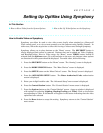


Section 2: Mounting and Wiring
2-5
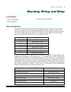
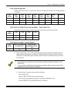
NTSC Output Configuration
Selects either one camera or guard tour (camera scanning) for default local viewing through
a monitor.
Dip
Switch
Cam-1
View
Cam-2
View
Cam-3
View
Cam-4
View
Cam-5
View
Cam-6
View
Guard
Tour
Reserved
1 OFF ON OFF ON OFF ON ON OFF
2 OFF OFF ON ON OFF OFF ON ON
3 OFF OFF OFF OFF ON ON ON ON
NTSC Guard Tour Mode (Camera Scanning Mode) – Camera Dwell Time
Selects the amount of time to remain on each camera before scanning to the next.
Dip
Switch
2 sec 4 sec 8 sec 16 sec
4 OFF ON OFF ON
5 OFF OFF ON ON
NTSC Guard Tour Mode – Camera Selection
Dip
Switch
Use All Six Cameras
for Guard Tour
Use First Four
Cameras for Guard
Tour
6 OFF ON
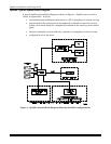
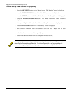
8. Turn on the power source. Wait approximately 30 seconds while the Optiflex software
loads and the video sources are detected. During this time Optiflex scans for cameras,
and if they are detected begins monitoring them. If they are not detected, they will not
be monitored.
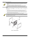
• During the boot-up process the cover should be removed to enable the installer to view
status LEDs.
• If a new camera is added after the initial boot–up process, power must be turned off and
reapplied for the new camera to be detected.
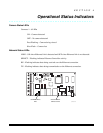
9. After the unit is powered up, check the following:
Power LED is ON.
Camera LED is ON for each connected camera.
If connected to the Ethernet hub/router Network LINK LED is ON.
Network SELECT, TX and RX LEDs may be flashing.