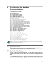
6 Configuring the Modbus
Communications
The subsections are as follows:
6.1: Base Radio Setup
6.1.1: Modbus Baud Rate Setting
6.1.2: Modbus Device ID Setting
6.1.3: Modbus Parity Setting
6.1.4: Modbus Mapping Mode Setting
6.2: Modbus Communication Protocol
6.3: Modbus Commands
6.3.1: Command 03-Read Holding Registers
6.3.1.1: Base Radio Holding Registers
6.3.1.1.1: Base Radio Device Type Holding Registers
6.3.1.1.2: Base Radio Device Status Holding Registers
6.3.1.1.3: Base Radio On/Offline Transmitter Registers
6.3.1.2: Transmitter Holding Registers
6.3.1.2.1: Transmitter Device Type Holding Registers
6.3.1.2.2: Transmitter Device Status Holding Registers
6.3.2: Command 08- Diagnostic
6.3.3: Command 11- Get Com Event Counter
6.3.4: Command 12- Get Com Event Log
6.3.5: Command 17- Report Slave ID
6.3.6: Command 43- Read Device ID
6.4: Base Radio Holding Registers
6.4.1: Base Radio Device Type Registers
6.4.2: Base Radio Device Status Registers
6.4.3: Base Radio On/Offline Transmitter Registers
6.5: Transmitter Holding Registers
6.5.1: Device ID Mapping Mode
6.5.2: Register Mapping Mode
6.5.3: Transmitter Device Type Holding Registers
6.5.4: Transmitter Device Status Registers
Note This device supports Modbus RTU (Binary) communications. Note that the ASC-II
transmission mode is not supported.
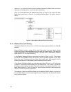
6.1 Base Radio Setup
The purpose of this section is to guide you through the configuration of the Base Radio in
order to enable communications with your particular Modbus Protocol.
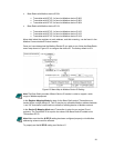
6.1.1 Modbus Baud Rate Setting
In order for the Base Radio to communicate with other devices, such as the server
computer or an existing PLC/DCS system, they must share the same Modbus Baud
Rate.
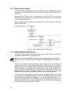
To set the Modbus Baud Rate, first determine which rate your system requires. If your
system will allow any baud rate, we suggest you use the fastest setting; however, some
systems cannot handle these faster baud rates due to external noise and transmission
22


