41316-01 • 09/17/10 • Hunter Fan Company
7
4 • Receiver Installation
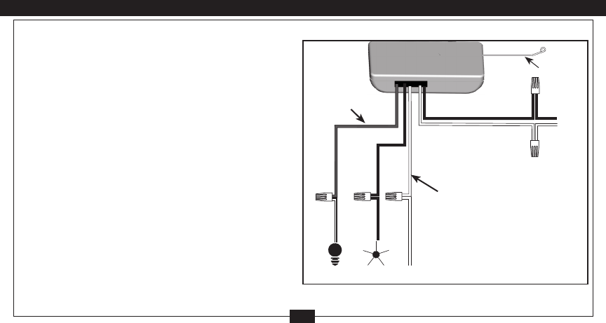
6. Use the 2 large (orange) wire connectors supplied to connect
the receiver and house wiring, then use the 3 small (blue)
wire connectors supplied to connect the receiver and ceiling
fan wiring. Refer to Wiring Diagram in Figure 9.
If you are installing the remote with a Hunter Fan, the wire
colors in the fan will be as follows:
Light Power = Black with a White Stripe
Fan Power = Black
Common = White
*These are only the Hunter fan wire colors. Other brands may
use different colors.
7.Veillezàbienxerl’antennedemanièreàcequ’ellenesoit
pas dans le chemin du ventilateur en mouvement. Référez-
vousàlagure9.Nemodieznin’endommagezlelde
l‘antenne car cela réduirait la performance de la commande.
Aprèsavoirxélerécepteur,l’antenneetlecâblage,terminez
la suspension du ventilateur de plafond selon les instructions.
8.Réenclenchezl’électricitéautableauélectriqueprincipal.
Antenne
Entrée
do
courant
alternatif
Commun
Ventiladeur
Luminaire
Noir/Sous Tension (identié
« LIVE IN [entrée sous-tension]
» sur l’étiquette rouge)
Blanc/Neutre (identié
« NEUTRAL IN [entrée
neutre] » sur l’étiquette
rouge)
Figure 9
SchémadeCâblage
Blanc (identié « LIGHT
AND FAN COMMON
[commun lumière et
ventilateur] » sur
l’étiquette blanche)
Noir
(“FAN
OUT”)
Rouge
(“LIGHT
OUT”)
Noir*
Noir et
Blanc*
Blanc*


