Netfinity EXP300 Type 3531 17
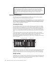
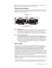
Fault LED (amber)
When lit, this amber LED indicates an ESM board failure.
SCSI reset LED
When lit, this green LED indicates a SCSI bus reset.
Push pins Each ESM board has an orange push pin to the bottom left of the board.
Use the orange push pin and lever to remove and insert the ESM board.
Termination-power LED (green)
When lit, this green LED indicates that termination power is present. (When
a termination-power LED is lit, it indicates that the other end of the cable is
connected to a powered-on controller.) Each external bus has a separate
termination-power LED.
LVD/SE LED (green)
When lit, this green LED indicates that the external host bus is in low voltage
differential (LVD) mode. When this LED is off, this indicates that the external
host bus is in single-ended (SE) mode. Each external bus has a separate
LVD/SE LED. Only LVD host bus controllers are supported.
SCSI bus connector
The 68-pin Very High Density Connector Interface (VHDCI) connectors are
for attaching your SCSI cables to SCSI bus 1 and SCSI bus 2.
Activity LED (green)
When lit, this green LED indicates there is activity on the external SCSI bus.
Each external bus has a separate activity LED.
Working with hot-swap drives
This section explains how you can increase the expansion unit capacity by adding
more drives or replacing existing drives with larger capacity drives.
Before you install or remove drive CRUs, review the following information:
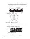
Hot-swap hardware
You can replace a failed hard disk drive without turning off the expansion
unit. Therefore, you can continue to operate your system while a hard disk
drive is removed or installed. These drives are known as hot-swap drives.
Drive CRUs Your expansion unit supports IBM Ultra160 and IBM Ultra2 SCSI hard
disk drives. These IBM drives come pre-installed in a drive tray, ready for
installation. (Do not detach the drive from the tray.) This drive and tray
assembly is called a drive customer replaceable unit (CRU). You can install the
drive CRUs directly into the 14 drive bays on the front of the expansion unit.
Be sure to record the location information for each drive before you remove it.
Ensure that you keep track of the drives and their corresponding bays.
Before you begin
• Read the safety and handling guidelines provided in “Safety information” on
page 41 and "Handling electrostatic discharge-sensitive devices."
• Ensure that your current system configuration is working properly.
• Back up all important data before you make changes to storage devices, such
as hard disk drives.


