


Intel
®
Server System SR1500AL User’s Guide 7
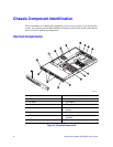
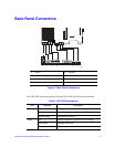
Server Board Connector and Component
Locations
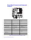
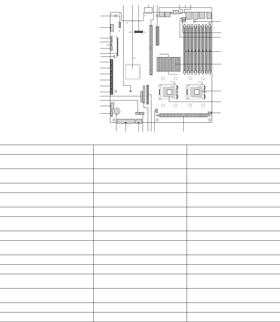
Figure 3. Server Board Connector and Component Locations
TP02071
M
N
O
L
J
K
V U
S
T
R
W
Q
P
PP
MM
LL
KK
II
HH
GG
FF
EE
DD
CC
BB
AA
Z
Y
X
B
A
ED
F
H
G
C
I
NN
OO
QQ
JJ
A. BIOS Bank Select Jumper B. Intel
®
6321ESB IO Controller Hub C. I/O Expansion Module Connector
D. POST Code Diagnostic LEDs E. Intel
®
Adaptive Slot - Full Height F. PCI Express* Riser Slot - Low
Profile
G. Rear System Identification LED -
Blue
H. Back Panel I/O Ports I. Status LED - Green/Amber
J. Serial B Configuration Jumper K. System Fan 4 Header L. System Fan 3Header
M. DIMM Sockets N. Intel
®
5000P MCH or Intel
®
5000X
MCH
O. Processor 1 Socket
P. Processor 2 Socket Q. Processor Fan 1 Header R. Voltage Regulator Heat Sink
S. Processor Fan 2 Header T. Bridge Board Connector U. ATA-100 Optical Drive Connector
(Power + IO)
V. System Fan 2 Header W. CPU Power Connector X. Main Power Connector
Y. Battery Z. Power Supply Management
Connector
AA. Dual Port USB 2.0 Header
BB. System Fan 1 Header CC. 24-pin SSI Control Panel Connector DD. SATA Port 0
EE. SATA Port 1 FF. SATA Port 2 GG. SATA Port 3
HH. SATA Port 4 II. SATA Port 5 JJ. SATA SW RAID 5 Activation Key
Connector
KK. Intel
®
Remote Management Module
(RMM) Connector
LL. System Recovery Jumpers MM. Chassis Intrusion Switch Header
NN. 3-pin IPMB Header OO. Intel
®
Local Control Panel Header PP. Serial A Header
QQ. Intel
®
RMM NIC Connector