14
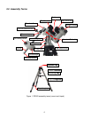
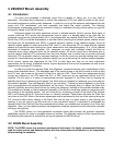
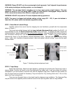
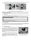
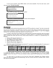
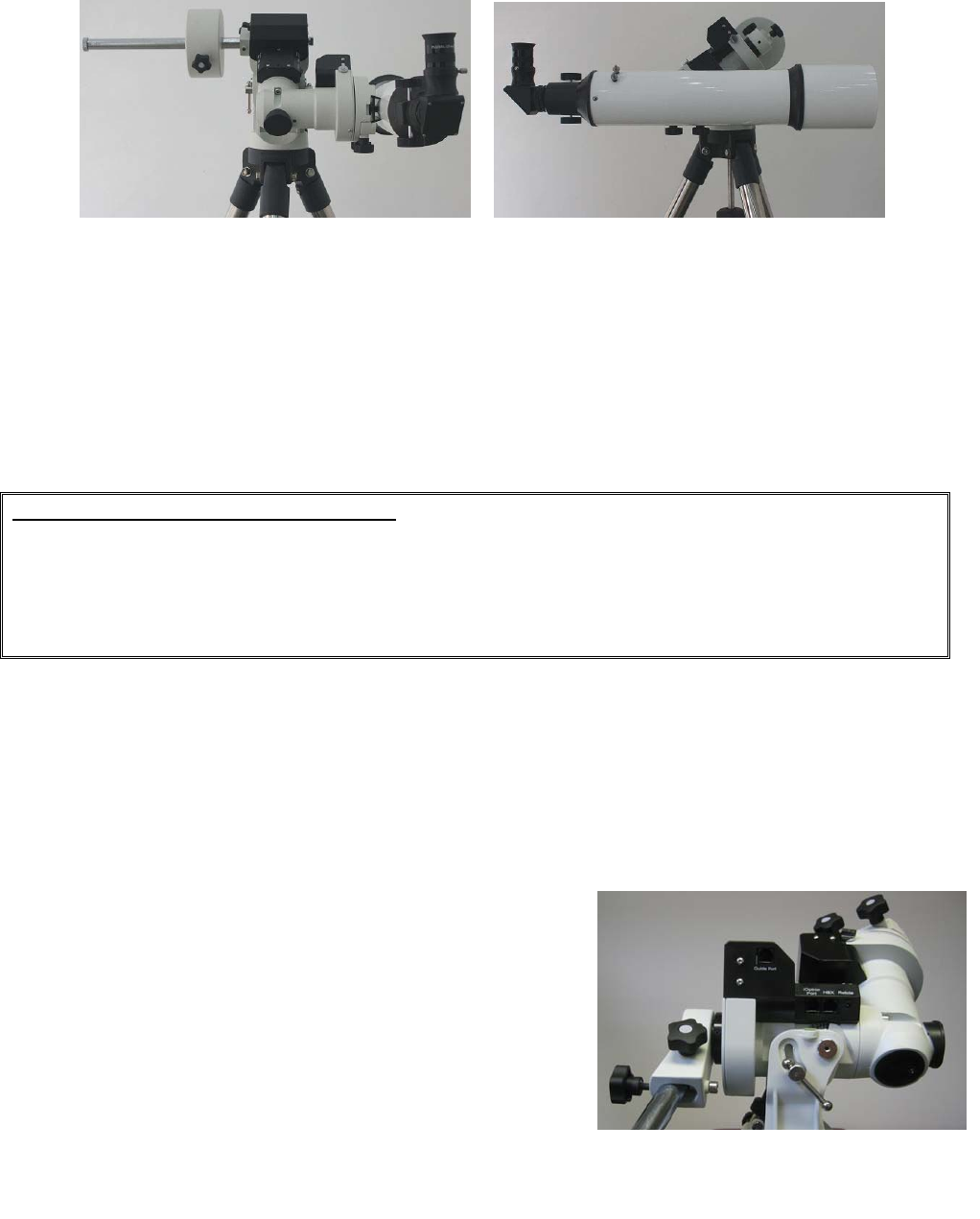
Rotate the DEC axis to horizontal position. Adjust the CW position to balance the mount in R.A. axis
(Figure 14a) and move the OTA position to balance the mount along DEC axis (Figure 14b).
(a) (b)
Figure 14. Balance along R.A. axis (a) and DEC axis (b)
CAUTION: The balance process MUST be done with Gear Switch at OPEN position! Otherwise it
might damage the worm system.
Return the mount to Zero Position after balance, i.e. the CW shaft points to ground and telescope is
at the highest position.
Turn Gear Switch Knob by 90° to LOCK position to re-engage the worm to the worm wheel.
Retighten the Tension Adjuster as the last step to lock the gear.
Important Notes on Tension Adjusters
The rule of thumb is to fully screw in the Tension Adjuster and then back out by about 2 turns. The
optimum spot varies with actual conditions, but is mostly within 1-3 turns from the fully tightened
position. Ideally, it should be at a position just deep enough to rid any free movements (plays), while
force on the worm assembly is kept at a minimum.
STEP 8. Connect Cables
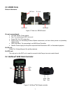
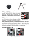
Connect DEC unit to the main control unit with a short, straight RJ11 cable. Connect the Go2Nova
®
8408 hand controller to the HC port on the main unit. Plug 12V DC power supply into the POWER socket.
The power indicator on the main unit will be on when the power switch is turned on.
STEP 9. Setup Hand Controller
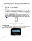
The ZEQ25 is equipped with a GPS receiver, which will
receive the time, longitude and latitude information from
satellites after the link is established. However, there are still
some parameters need to be entered to reflect your location,
such as time zone info and daylight saving time. The
information will be stored inside the hand controller memory
along with longitude and latitude coordinates until they need to
be changed.
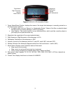
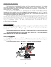
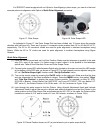
A clear sky and open space outside is needed for the
GPS to establish its link with the satellites. The GPS is
installed inside main control board compartment. If it has
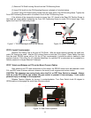
difficulty to receive the GPS signal, you may turn the mount
head 90º to the side of the mount to clear the space on top of
the main board.
Figure 15. Rotate mount head 90º to
clear the space for GPS receiver


