


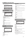

DC IN
(12V)
PC IN
D-SUB
15 PIN
DC IN
(19V)
PC IN
D-SUB
15 PIN
S-VIDEO
VIDEO
L/MONO
R
Y
Pb/Cb
R
COMPONENT
VIDEO-1
PC
AUDIO
IN
AUDIO
OUT
R L
SUBWOOFER
OUT
VIDEO
L/MONO
R
Y
Pb/Cb
Pr/Cr
R
VIDEO-1
LT-26C31BUE/SUE/BJE/SJE / LCT1484-001A-U / English (EK)
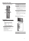
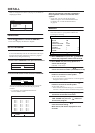
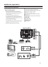
Additional preparation
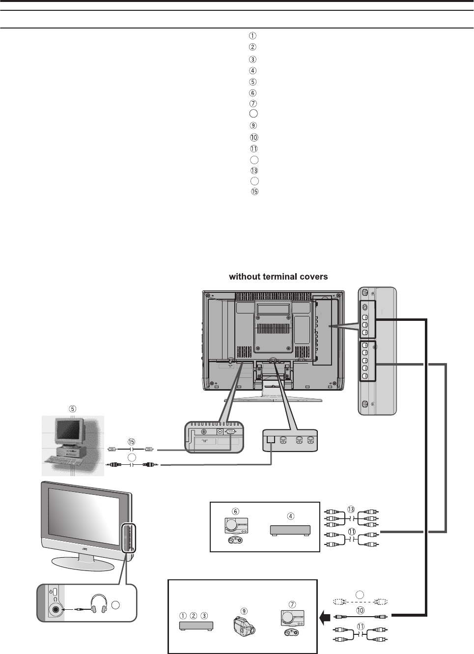
Connecting external equipment
Connect the equipment to the TV, making the correct rear
panel and front panel connections.
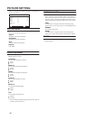
Before connecting anything:
• Read the manuals that came with the equipment.
Depending on the equipment, the connection method
may be different from the diagram. Also, the equipment
settings may need to change depending on the
connection method.
• Turn off all the equipment including the TV.
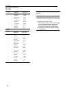
• The “Specifications” on page 29 give the details of the
EXT terminals. If you are connecting equipment not
listed in the following connection diagram, see the table
to choose the best EXT terminal.
• Connecting cables are not supplied.
VCR (composite signal)
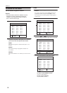
VCR (composite signal/S-VIDEO signal)
DVD player (composite signal/S-VIDEO signal)
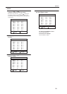
DVD player (component
signal)
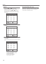
TV game
TV game (composite signal/S-VIDEO signal)
Headphones
Camcorder (composite signal/S-VIDEO signal)
Component cable
Video cable
S-VIDEO cable
D-SUB cable
LT-26C31BUE(EK)_Eng.book Page 33 Tuesday, August 5, 2003 2:18 PM
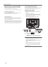
L
PC AUDIO IN
SUBWOOFER
R
PC
Stereo mini jack
12
DC IN
(12V)
PC IN
D-SUB
15 PIN
(component
signal)
Audio cable
14
8
27
12
8
14
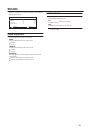
•
If the VCR'saudio output is in mono, connect the VCR's
AUDIO OUT (audio output) terminal and TV's Audio
L/MONO input terminal with an audio cable.
•
Progressive scanning singnals are not availavle.
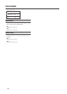
S-VIDEO
VIDEO
VIDEO
AUDIO
COMPONENT
(VIDEO-2)
AUDIO
L/MONO
VIDEO
AUDIO
(VIDEO-2)
Pr/Cr
L/MONO
AUDIO