


Masterpage:Right0
EN 19
Filename [DR-MH30EU_04Name.fm]
Page 19 Thursday, 3 June 2004 10:46
INSTALLING YOUR NEW UNIT
It’s essential that your unit be properly connected.
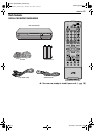
1 Place the unit on a stable, horizontal surface.
2 Connect the unit to a TV depending on the TV and cables you
use.
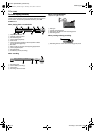
8 Basic Connection
To connect to a TV with 21-pin SCART input connector —
A Disconnect the TV aerial cable from the TV.
B Connect the TV aerial cable to the ANTENNA IN connector on
the rear panel of the unit.
C Connect the ANTENNA OUT connector on the rear panel of the
unit and the TV’s aerial connector with the provided RF cable.
D Connect the L-1 IN/OUT connector on the rear panel of the unit
and the TV’s 21-pin SCART connector with a provided 21-pin
SCART cable.
● The L-1 IN/OUT connector accepts and delivers either a composite
signal (regular video signal), Y/C signal or RGB signal.
● Set your TV to the VIDEO (or AV), Y/C, or RGB mode according to
the type of your TV’s SCART connector.
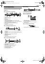
8 S-Video Connection
To connect to TV’s S-VIDEO input and AUDIO input
connectors —
A Perform A – C in “Basic Connection”.
B Connect the unit’s S-VIDEO OUT connector to the TV’s
S-VIDEO input connector.
C Connect the unit’s AUDIO OUT connectors to the TV’s AUDIO
input connectors.
● You can obtain high-quality S-VHS pictures.
● With S-VIDEO connection, you cannot use the Preset Download
function. (
੬ pg. 21)
● If your TV is not stereo-capable, use the unit’s AUDIO OUT
connectors to connect to an audio amplifier for Hi-Fi stereo sound
reproduction.
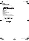
8 Component Video Connection
To connect to TV’s component video input connectors —
A Perform A – C in “Basic Connection”.
B Connect the unit’s COMPONENT VIDEO OUT connectors to
the TV’s component video input connectors.
C Connect the unit’s AUDIO OUT connectors to the TV’s AUDIO
input connectors.
● You can obtain high-quality component video pictures.
● If your TV is not stereo-capable, use the unit’s AUDIO OUT
connectors to connect to an audio amplifier for Hi-Fi stereo sound
reproduction.
● By using the component video connection, you can view the images
in the progressive mode. For switching to the progressive mode, refer
to “Scan Mode Set” (੬ pg. 71).
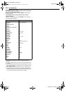
NOTE:
Select an appropriate option of “L-1 OUTPUT” as follows (੬ pg. 63):
3 Plug the end of the mains power cord into a mains outlet.
● “LOADING” blinks on the front display panel when the AC plug of the
mains power cord is connected into a mains outlet and it takes
approximately 50 seconds for the unit to be turned on. This is not a
malfunction.
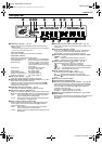
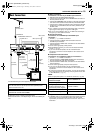
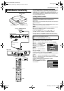
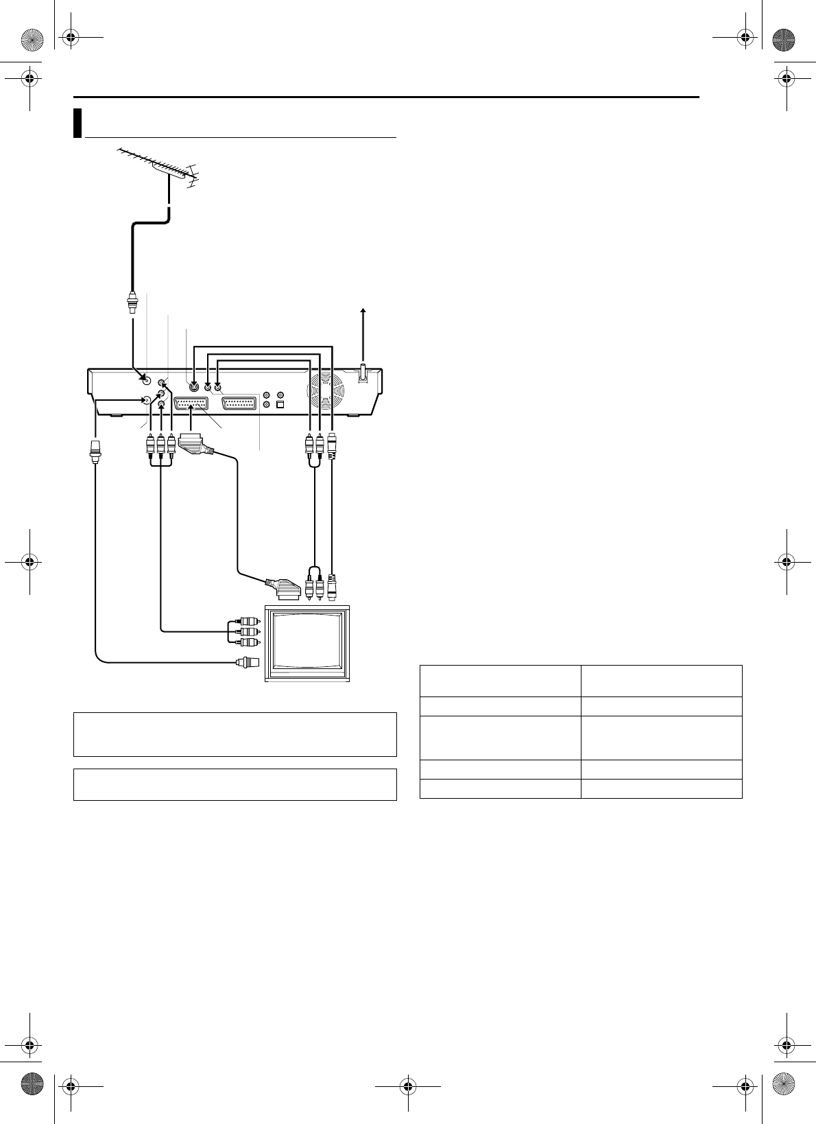
Basic Connections
A
TTENTION:
Your TV must have a 21-pin AV input connector (SCART) for the
basic connection to the unit.
THESE STEPS MUST BE COMPLETED BEFORE ANY VIDEO
OPERATION CAN BE PERFORMED.
TV aerial cable
Mains outlet
Back of unit
Component
video cable
(not provided)
TV
Mains power cord
Audio cable
(not provided)
S-Video
cable
(not
provided)
COMPONENT VIDEO OUT
AUDIO OUT
ANTENNA IN
ANTENNA
OUT
RF cable
(provided)
S-VIDEO OUT
L-1 IN/OUT
21-pin SCART
cable
(provided)
When your TV’s SCART
connector accepts:
Set “L-1 OUTPUT” to:
Composite signals “SCART VIDEO”
Y/C signal (separated
luminance (brightness) and
chrominance (colour) signals)
“SCART S-VIDEO”
RGB signal “SCART RGB”
Component video signal “COMPONENT”
DR-MH30EU_00.book Page 19 Thursday, June 3, 2004 11:00 AM