7
R
Installations
Make sure that the power to the video cassette recorder and TV
is off before making the following connections.
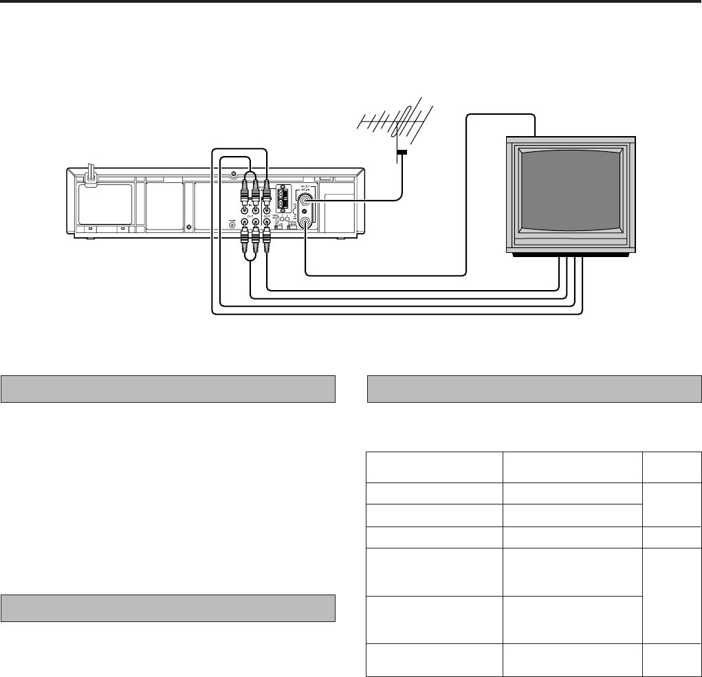
Connection A (basic)
In order to use the video cassette recorder it must be connected
between the antenna and the TV.
Connect your TV antenna cable to the video cassette
recorder’s antenna input terminal.
Connect one end of the provided RF antenna cable to
the video cassette recorder’s RF output terminal and
the other end to the TV’s antenna terminal.
Connect the power cord to your household AC outlet.
1
2
3
Select television system
Set the SYSTEM switch to the appropriate position
according to your TV system. (Refer to the chart below.)
Connection B
For connection with a TV that has VIDEO/AUDIO IN/OUT
terminals. Use RCA type pin connection cords (available from
audio/video stores) for connection. This connection is in addition
to connection A.
Follow steps 1 and 2 of “Connection A”.
Connect the TV’s VIDEO output and AUDIO output
terminals to the video cassette recorder’s VIDEO input
and AUDIO input terminals.
Connect the TV’s VIDEO input and AUDIO input
terminals to the recorder’s VIDEO output and AUDIO
output terminals.
Connect the power cord to your household AC outlet.
Note:
• Use the conversion plug (provided) depending on the type of
your AC wall outlet.
1
Connection A
4
1
2
3
Major countries
China, Mongolia
Russia
Hong Kong
Kuwait, U.A.E,
Indonesia, Singapore,
Thailand, Malaysia
Iran, Saudi Arabia,
Egypt, Morocco,
Lebanon, Iraq
U.S.A., Japan,
S. Korea, Taiwan
Switch
position
K
I
G
M
Colour TV broadcast
system
PAL D/K
SECAM D/K
PAL I
PAL B/G
SECAM B/G
NTSC M
Notes:
• If no colours appear on the screen when using a multi-
system television with its system select switch set to AUTO,
change the switch position to correspond to the recorder’s
RF system select switch (K, I, G or M).
• For more information on multi-system compatibility. ੬ p.25
Connection B


