


10
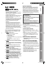
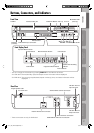
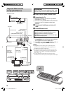
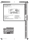
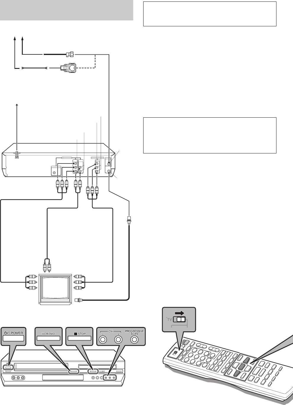
Component Video Connection
(For high-quality DVD pictures)
Antenna or Cable
Coaxial cable
Flat feeder
AC Outlet
Matching transformer
(not supplied)
AC Power Cord
VHF/UHF
OUT
AUDIO OUTPUT
VHF/UHF
IN
Back of unit
Audio/video
cable
(not supplied)
To Component
Video/audio Input
connector
RF cable
(supplied)
To 75 ohm Terminal
TV
COMPONENT VIDEO OUT
Component
Video cable
(not supplied)
ATTENTION
Be sure to connect the unit’s VIDEO OUTPUT (DVD/
VCR) connector to the TV’s VIDEO input connector.
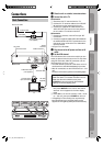
~ Place the unit on a stable, horizontal surface.
Ÿ Connect the unit to TV.
1 Connect the antenna, unit and TV as per “Basic
Connections.” (☞ pg. 9)
2 Connect the unit’s COMPONENT VIDEO OUTPUT
connector to the TV’s component video input
connector.
! Plug the end of the AC power cord into an AC
outlet.
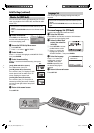
⁄ Set the VCR channel to off.
Before performing the following steps:
• Make sure there is no cassette inserted in the unit.
• Make sure the unit is turned on, then press
VCR/DVD on the unit so that the VHS indicator lights
up on the front display panel.
1 Press POWER on the unit to turn off the unit, then
press 7 STOP on the unit for more than 5 seconds.
“3 CH” appears on the front display panel.
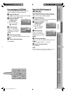
2 Press CH +/– on the unit to select “3 CH,” “4 CH,” or
“– CH” (off), then press POWER on the unit.
NOTES:
• If Plug&Play or Tuner setting has not previously been
performed, the Language Select screen appears and
Plug&Play takes place automatically.
• By using the component video connection, you can view
the images in the progressive mode. For switching to the
progressive mode, refer to “Scan Mode Set (DVD deck
only).” (☞ pg. 11)
• To enjoy playback of DVD with the component video
connection, set the TV’s input to the component video input.
Audio cable
(not supplied)
To Audio/video
input connectors
AUDIO OUTPUT
VIDEO OUTPUT
04-11_EN_HR-XVC29SUM.indd 1004-11_EN_HR-XVC29SUM.indd 10 05.6.3 9:11:44 PM05.6.3 9:11:44 PM