


Filename [MX1SEU_05Name.fm]
Masterpage:Left0
16 EN
Page 16 Monday, 6 December 2004 14:00
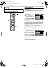
INSTALLING YOUR NEW UNIT
It’s essential that your unit be properly connected.
1 Make sure the package contains all of the accessories listed in
ASPECIFICATIONSB (A pg. 94).
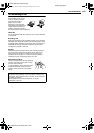
2 Place the unit on a stable, horizontal surface.
3 Connect the unit to a TV depending on the TV and cables you
use.
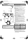
8 Basic Connection
To connect to a TV with 21-pin SCART input connector ^
A Disconnect the TV aerial cable from the TV.
B Connect the TV aerial cable to the [ANTENNA IN] connector on
the rear panel of the unit.
C Connect the [ANTENNA OUT] connector on the rear panel of
the unit and the TV’s aerial connector with the supplied RF
cable.
D Connect the [L-1 IN/OUT] connector on the rear panel of the
unit and the TV’s 21-pin SCART connector with a supplied 21-
pin SCART cable.
● The [L-1 IN/OUT] connector accepts and delivers either a
composite signal (regular video signal), Y/C signal or RGB
signal.
● Set your TV to the VIDEO (or AV), Y/C, or RGB mode
according to the type of your TV’s SCART connector.
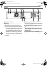
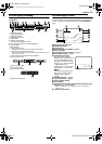
8 Component Video Connection
To connect to TV’s component video input connectors ^
A Perform A – C in ABasic ConnectionB.
B Connect the unit’s [COMPONENT VIDEO OUT (Y/P
B
/P
R
)]
connectors to the TV’s component video input connectors.
C Connect the unit’s [AUDIO OUT] connectors to the TV’s AUDIO
input connectors.
● You can obtain high-quality component video pictures.
● If your TV is not stereo-capable, use the unit’s [AUDIO OUT]
connectors to connect to an audio amplifier for Hi-Fi stereo
sound reproduction.
● By using the component video connection, you can view the
images in the progressive mode. For switching to the
progressive mode, refer to AScan Mode SetB (A pg. 89).
● You can also watch the images on the VHS deck in Progressive
scan mode via the component video output, refer to AVHS
Progressive ScanB (A pg. 43).
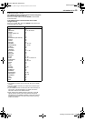
NOTE:
Select an appropriate option of AL-1 OUTPUTB as follows
(A pg. 72):
When the setting selected is not in accordance with the TV
connected and depending on the type of appliance connected to
the unit, the correct picture will not appear.
4 Plug the end of the mains power cord into a mains outlet.
● ALOADINGB blinks on the front display panel when the AC plug
of the mains power cord is connected into a mains outlet and it
takes approximately 50 seconds for the unit to be turned on.
This is not a malfunction.
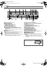
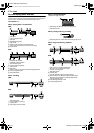
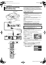
Basic Connections
ATTENTION:
● Your TV must have a 21-pin AV input connector (SCART) for
the basic connection to the unit.
● Connect the AC plug only after all connections to the TV has
been completed.
TV aerial cable
Mains outlet
Back of unit
Component
video cable
(not supplied)
TV
Mains power cord
Audio cable
(not supplied)
To [COMPONENT
VIDEO OUT (Y/P
B
/
P
R
)]
To [AUDIO
OUT]
To [ANTENNA IN]
To
[ANTENNA
OUT]
RF cable
(supplied)
To [L-1 IN/
OUT]
21-pin SCART
cable
(supplied)
To 75 ohm
terminal
THESE STEPS MUST BE COMPLETED BEFORE ANY VIDEO
OPERATION CAN BE PERFORMED.
When your TV’s SCART
connector accepts:
Set AL-1 OUTPUTB to:
Composite signals ASCART VIDEOB
Y/C signal (separated
luminance (brightness) and
chrominance (colour) signals)
ASCART S-VIDEOB
RGB signal ASCART RGBB
Component video signal ACOMPONENTB
MX1SEU_00.book Page 16 Monday, December 6, 2004 2:01 PM