


Masterpage:Right+
EN 11
Filename [DVM700EU_05Name.fm]
INDEX
Page 11 Wednesday, 20 September 2006 10:02
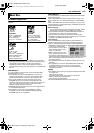
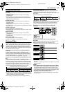
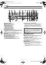
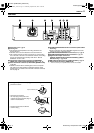
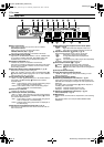
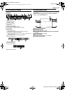
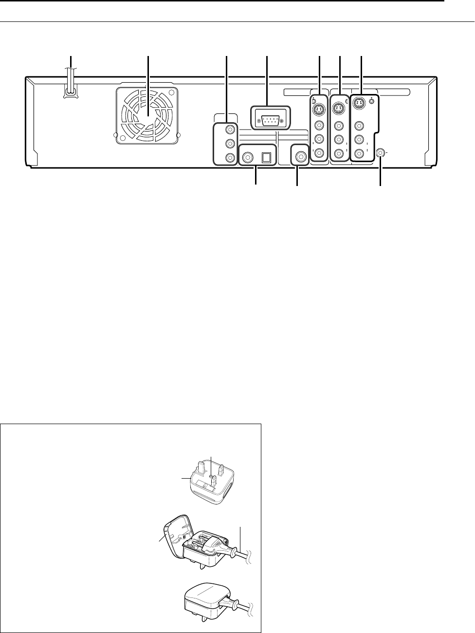
Rear View
A AC Power Cord A pg. 16
B Cooling Fan
● This prevents the temperature from rising inside the unit.
Do not remove it.
● Install the unit so as not to block the area around the fan.
● The unit may become hot when it is turned off, as the cooling
fan on the rear of the unit is not activated. However, the cooling
fan may be activated in the standby mode when AQUICK
STARTUPB is set to AONB.
C Component Video Output Connectors [COMPONENT
VIDEO OUT (Y/P
B
/P
R
)] (HDD & DVD deck only) A pg. 16
D Serial Command Connector (D-SUB 9-PIN) [SERIAL COM.]
A pg. 70
● Use this connector when controlling this unit via a computer.
The cable to be used should be a RS-232C interface cable
(straight type). For details on the RS-232C interface command,
refer to page 70.
E S-VIDEO/VIDEO/AUDIO OUTPUT Connectors (HDD & DVD
deck only)
● These connectors only output DVD/HDD signals and can be
used to connect to a second monitor.
F S-VIDEO/VIDEO/AUDIO INPUT Connectors (L-1) A pg. 51
G S-VIDEO/VIDEO/AUDIO OUTPUT Connectors A pg. 16
H Digital Audio Output Connectors
[DIGITAL AUDIO OUTPUT (OPTICAL/COAXIAL)] (HDD &
DVD deck only) A pg. 52, 56
I BNC Video Output Connector [VIDEO OUTPUT] A pg. 16
J Remote Input Connector* [REMOTE IN]
* There is currently no compatible remote control unit available.
OUTPUT
DV/HDD/DVD
INPUTL-1
OPTICAL
HDD/DVD
L
R
DIGITALAUDIOOUT
COMPONENT
VIDEOOUT
VIDEO
AUDIO
VIDEO
AUDIO
PCM/STREAM
L
R
VIDEO
COAXIAL
SERIALCOM.
Y
P
B
PR
REMOTEIN
OUTPUT
HDD/DVD
L
R
AUDIO
VIDEO
S-VIDEO
DV/HDD/DVD
OUTPUT
S-VIDEO
S-VIDEO
BCA
H
I
D
E GF
J
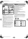
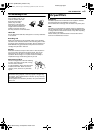
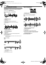
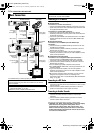
Installing the 3-pin conversion plug (For UK use only)
A Remove the screw.
B Open the lid, and place
the 2-pin plug of the power cord
properly into the conversion plug as
shown in the illustration.
C Close the lid and secure with the
screw in step A.
3-pin conversion plug
Screw
Power cord
Lid
DVM700EU_00.book Page 11 Wednesday, September 20, 2006 10:02 AM