


TM-2001U
TM-2701SU
23
L/ MONO
R
75Ω
(VHF/UHF)
INPUT
AUDIO OUT
S-VIDEO
VIDEO
OVER
L
R
Yellow
White
Red
IN
IN
IN
L/ MONO
R
L
IDEO
IN
OUT
VCR
Video
Audio
VIDEO
EQUIPMENT
BNC
Connector
box
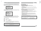
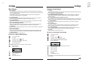
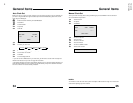
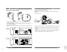
1 Connect a white audio cable from the VCR Left Audio output the TV's Left Audio input
jack.
2 Connect the red audio cable from the VCR Right Audio output the TV's Right Audio
input jack.
3 Connect the video cable (BNC) from the VCR output into the input of the BNC connec-
tor box.
4 You can send the video signal from the VCR to another pice of video equipmnt by
plugging a cable into the output jack of the BNC connector box.
The IN and OUT terminals are bridge-connected.
(When no cable is connected to the OUT terminal, the input signal is automatically
terminated.)
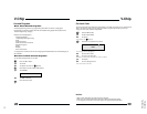
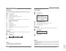
Illustration of TM-2701SU
Bridge-connection
45
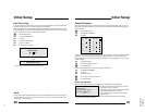
1 Slide the claps on the BNC connector box into the slots at the back of the television
until it clicks into position.
2 Connect the cable out from the bottom of the BNC connector box into the Video Input
jack at the rear of the televition.
3 Use the BNC connectior box as the input jask for the television for any video-in connec-
tions.
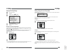
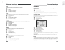
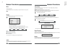
TM-2001U
Rear panel
TM-2701SU
Rear panel
IN
OUT
IN
VIDEO
L
AUDIO
R
OUT
IN
OUT
NOTICE
CONNECT THE BNC CONNECTOR
BOX (AUTO TERMINATION). THIS
VIDEO-IN JACK (RCA) IS
NOT
TERMINATED 75 Ω
L/ MONO
R
75Ω
(VHF/UHF)
INPUT
AUDIO OUT
S-VIDEO
VIDEO
OVER
L
R
IN
OUT
NOTICE
CONNECT THE BNC CONNECTOR
BOX (AUTO TERMINATION). THIS
VIDEO-IN JACK (RCA) IS
NOT
TERMINATED 75 Ω
BNC connection box installation
BNC connector box
1
2
3
44