6
206-4122
Setup Information
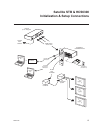
Check the following items before you begin HCS6300 installation and setup procedures.
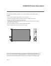
HCS6300
__ The HCS6300 feature card must be installed in a CodePlus™ card frame (Example:
HCS6150R) with one or more CodePlus series transcoder cards (Example: HCS7710).
Refer to the Installation & Setup Guide for the card frame to verify that the chassis is
installed properly. Note: All cards must be used in an LG-approved card frame for
this product.
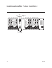
__ The HCS6300 must be installed in the card frame CONTROLLER slot. If another
CodePlus feature card is currently installed in the CONTROLLER slot, the HCS6300 will
replace it.
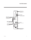
__ The HCS6300 ships with an HCS6400 fan card. In an HCS6100R card frame, the
HCS6400 fan card must be installed in Slot 7. If another CodePlus card is currently
installed in Slot 7, the HCS6400 will replace it.
__ For HSC6300 Service Port connections, you must use an FTDI TTL-USB cable (P/N
TTL-232R-5V-AJ).
Channel Assignments
__ Create a channel assignment plan for the installation site, or modify an existing plan
to incorporate the RF output of the HCS6300. Ensure that up to four contiguous CATV
channels are allocated for the HCS6300 RF output. The HCS6300 uses a 256-QAM
modulation format, thereby occupying approximately 24 MHz of frequency spectrum.
The RF start channel is user-assigned during system setup, and the remaining channels
are then automatically assigned per EIA-542 STD CATV frequency allocation standards.
For example, if the RF start channel assignment is channel “2,” the three remaining
channels will be “3” “4” and “5.” However, if the RF start channel assignment is “6,” the
three remaining channels will be “95” “96” and “97.” Refer to EIA-542 STD CATV frequency
allocation tables for further information as required.
The highest available RF channel number for the HCS6300 is “135.” Thus, to allocate all
four channels available for HCS6300 RF output, the RF start channel must be set no
higher than “132.”
Transcoders
__ For HCS6300 MUX/MOD functionality, transcoder cards should be inserted in the
following slots: 1, 2, 4, 5, 8, 9, 11, and 12. Refer to the Installation & Setup Guide for the
transcoder cards to verify that the cards are installed properly.
__ In a CodePlus HCS6100R card frame, it is possible to install up to three additional
transcoders in the following slots: 3, 6, and 10. These additional transcoders must be
connected to external modulators and upconverters. Refer to the Installation & Setup
Guide for the transcoder cards for further information.


