


Page
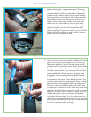
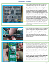
Turn the remote so that the logic board is face up.
There are three screws that need to be removed
so that the front cover can be separated from the
logic board. Two of the screws are near the bottom
of the remote on either side and the third screw is
almost dead-center just above the large silver-col-
ored component cover. These screws are shorter
than the screws you removed previously so do not
mix them up.
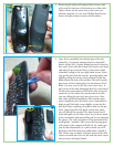
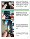
Now, the only other thing that needs to be done
before the logic board can be removed from the
front cover is to unclip the touch screen ribbon
cable. Flip the black connecting clamp up and
back. Do it gently and carefully since it can some-
times detach from the connector and be difcult to
put back on. Slide the ribbon cable out.
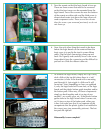
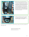
To remove the logic board, simply lift it up. It may
stick a little at the top left where there is a ‘soft’
connection (a hole in the board with a mounting
post through it). Just wiggle it a little and it will
come free. Now, depending on how you grabbed
it, only the logic board will come free, or the logic
board and the plastic button guide template and/or
the button pads. Either way, all these components
simply go back together and sit on top of one
another – no screws, glue, etc. If the plastic button
guide sticks to the logic board when it comes out,
or if it stays on top of the button pad, either way
is ne. Just make sure that if you separate all the
components that the plastic guide is re-installed in
the correct way (see reassembly pictures). The but-
ton pads lift right off.
Disassembly is now complete!
.
.
.