


31
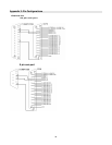
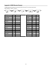
Pin References for RS-232 / Alarm Block
PIN 1. GND
GROUND
PIN 2. ALARM INPUT 8
Used to connect an alarm sensor between ALARM INPUT 8 (PIN 2) and GND (PIN 1) to trigger an alarm on Camera
8 which can activate the internal audible alarm and start recording.
PIN 3. ALARM INPUT 6
Used to connect an alarm sensor between ALARM INPUT 6 (PIN 3) and GND (PIN 1) to trigger an alarm on Camera
6 which can activate the internal audible alarm and start recording.
PIN 4. ALARM INPUT 4
Used to connect an alarm sensor between ALARM INPUT 4 (PIN 4) and GND (PIN 1) to trigger an alarm on Camera
4 which can activate the internal audible alarm and start recording.
PIN 5. ALARM INPUT 2
Used to connect an alarm sensor between ALARM INPUT 2 (PIN 5) and GND (PIN 1) to trigger an alarm on Camera
5 which can activate the internal audible alarm and start recording.
PIN 6. ALARM INPUT 16
Used to connect an alarm sensor between ALARM INPUT 16 (PIN 6) and GND (PIN 1) to trigger an alarm on
Camera 16 which can activate the internal audible alarm and start recording.
PIN 7. ALARM INPUT 14
Used to connect an alarm sensor between ALARM INPUT 14 (PIN 7) and GND (PIN 1) to trigger an alarm on
Camera 14 which can activate the internal audible alarm and start recording.
PIN 8. ALARM INPUT 12
Used to connect an alarm sensor between ALARM INPUT 12 (PIN 8) and GND (PIN 1) to trigger an alarm on
Camera 12 which can activate the internal audible alarm and start recording.
PIN 9. ALARM INPUT 10
Used to connect an alarm sensor between ALARM INPUT 10 (PIN9) and GND (PIN 1) to trigger an alarm on Camera
10 which can activate the internal audible alarm and start recording.
PIN 10. PIN OFF
PIN 11. RS232-TX
The DVR can be controlled remotely by an external device or control system, such as a control keyboard, using RS-
232 serial communications signals.
PIN 12. RS485-A
The DVR can be controlled remotely by an external device or control system, such as a control keyboard, using
RS485 serial communications signals.
PIN 13. EXTERNAL ALARM NO
Under normal operation COM disconnect with NO. But when Alarm triggered, COM connect with NO.
PIN 14. PIN OFF
PIN 15. ALARM INPUT 7
Used to connect an alarm sensor between ALARM INPUT 7 (PIN 15) and GND (PIN 1) to trigger an alarm on
Camera 7 which can activate the internal audible alarm and start recording.
PIN 16. ALARM INPUT 5
Used to connect an alarm sensor between ALARM INPUT 5 (PIN 16) and GND (PIN 1) to trigger an alarm on
Camera 5 which can activate the internal audible alarm and start recording.
PIN 17. ALARM INPUT 3
Used to connect an alarm sensor between ALARM INPUT 3 (PIN 17) and GND (PIN 1) to trigger an alarm on
Camera 3 which can activate the internal audible alarm and start recording.
PIN 18. ALARM INPUT 1
Used to connect an alarm sensor between ALARM INPUT 1 (PIN 18) and GND (PIN 1) to trigger an alarm on
Camera 1 which can activate the internal audible alarm and start recording.