


3
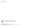
CONNECTORS AND DEFINITIONS
Please do not connect power to the STB until all other connections have been made.
C1: AC IN (Power Cord) Connect this to the power outlet (100-240 V AC 50/60 Hz)
C2: ON Power on / off switch
C3: TV OUT (UHF Output) Connect TV or VCR to this connector (OPTIONAL)
C4: ANTENNA IN Connect TV antenna to this connector (OPTIONAL)
C5: LNB IN (IF Input) Connect the cable from your LNB to this connector.
C6: LOOP OUT IF out to LNB input of another STB.
C7: S/P DIF Digital audio output for connecting to a digital audio decoder/amplifier.
C8: VCR SCART Connect VCR or DVD player via a SCART cable to this connector.
C9: TV SCART Connect TV via a SCART cable to this connector.
C10: AUDIO LEFT / RIGHT Audio outputs for connecting to a Hi-Fi System.
C11: VIDEO Composite video output to connect an AV monitor etc.
C12: RS-232 Connect PC to this connector. Use NULL MODEM (female to female) cable.
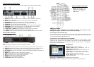
FRONT PANEL CONTROLS
Open flap (F10) from catch on left side to reveal the CA slots.
F1: Card Slot 1 (Plaza XT.M, Plaza XT.C and Plaza XT.CM) Insert smart card into this slot.
F2: Card Slot 2 (Plaza XT.M, Plaza XT.C and Plaza XT.CM) Insert smart card into this slot.
F3: CI Slot (Plaza XT.C) Insert CAM (type 1 or 2 PCMCIA modules) into this slot.
F4: LED Display Shows channel number or certain programming functions. In standby, it
shows the time.
F5: SIGNAL This indicator turns on when signal is present.
F6: STBY This indicator turns on when STB is switched to standby.
F7: ON This indicator turns on when STB is switched on.
F8: CH Down To step down channels sequentially.
F9: CH Up To step up channels sequentially.
F11: STBY/ON To switch STB to standby or on.
4
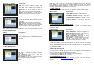
INSTALLATION
IMPORTANT: After configuring and exiting any menu, the prompt to save
message will appear. Press OK on ‘Yes’ to save the settings.
Connecting via the TV SCART (C9)
For clear picture quality, connect STB to your TV with a full SCART lead. Select AV input
on your TV and switch on the STB. After initializing the display (F4) will show “NOCH” and
your TV should show the OSD Setting menu.
Connecting via TO TV (UHF output C3) OPTIONAL
Connect to your TV with a UHF (co-axial) lead and switch on the STB. Select a spare
channel on your TV and tune it to channel 64 or until you see the OSD Setting menu.
Finally store the setting on your TV. The STB is factory set to channel 64. To change the
output channel, see TV Setting.
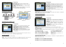
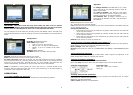
OSD Setting Configuration
Audio Lang / Subtitle Lang: Select default channel language.
Menu Color: Configure different color themes for OSD menus. See following.
Menu Lang: Select OSD language.
Display Level:
Select transparency level of
channel banner and browser.
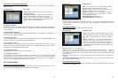
Display Time:
Select time out for banner. If ‘On’
is selected, it remains until EXIT key is pressed.
Signal Beep:
To control audio beep sound in
channel search when signal is present
Screen Saver:
Select time to switch on screen
saver for radio mode.
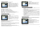
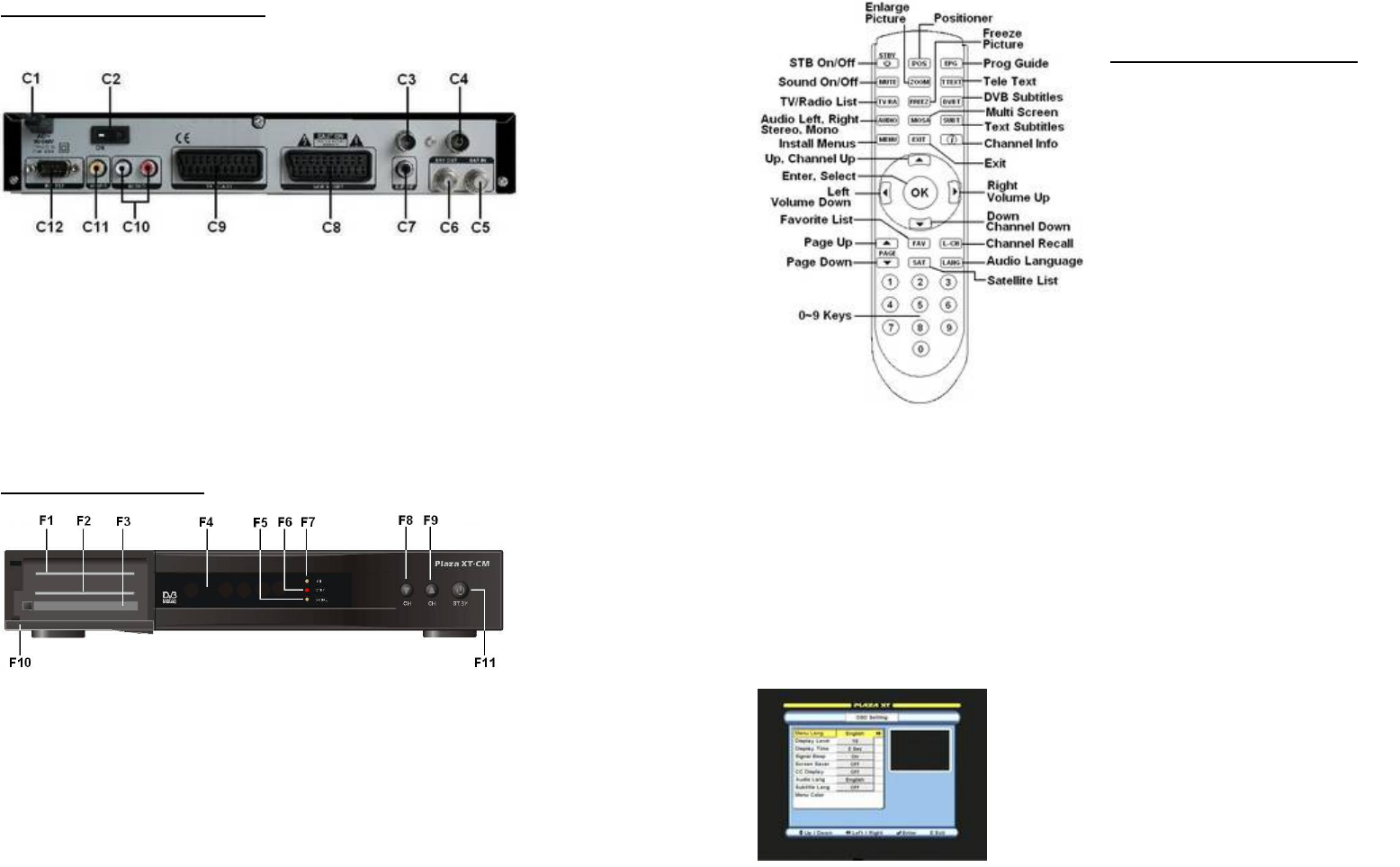
REMOTE CONTROL FUNCTIONS
NOTE:
POS Positioner key
is active only in DiSEqC 1.2
mode. It is not active in
USALS mode.