MAX12527
Applications Information
Using Transformer Coupling
In general, the MAX12527 provides better SFDR and
THD with fully differential input signals than single-
ended input drive, especially for input frequencies
above 125MHz. In differential input mode, even-order
harmonics are lower as both inputs are balanced, and
each of the ADC inputs only requires half the signal
swing compared to single-ended input mode.
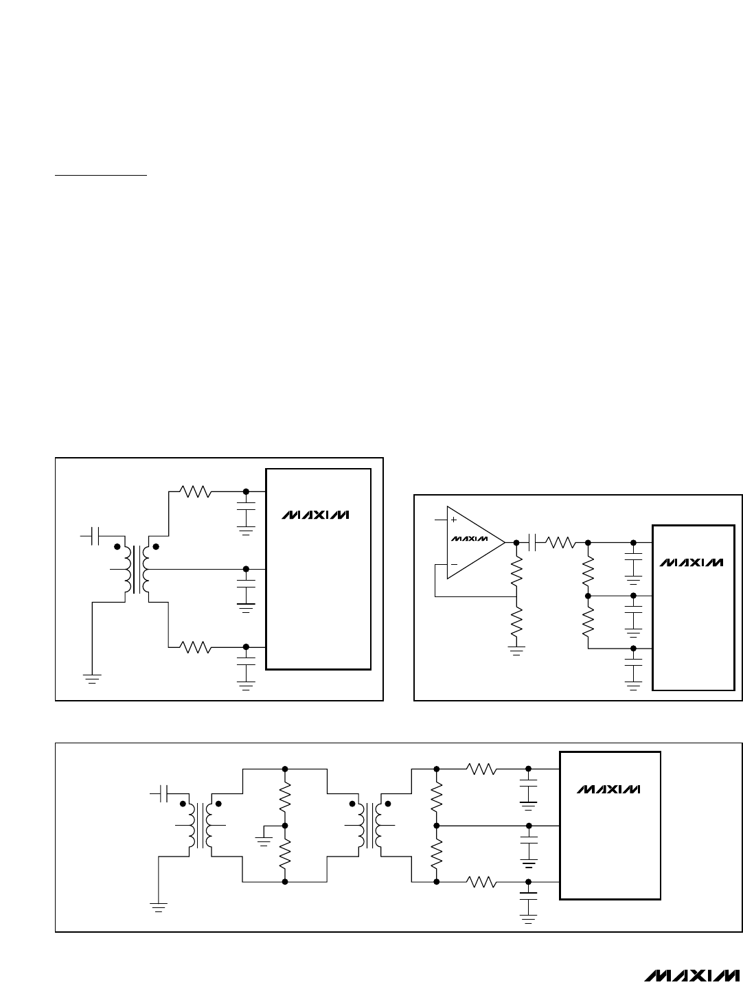
An RF transformer (Figure 9) provides an excellent
solution to convert a single-ended input source signal
to a fully differential signal, required by the MAX12527
for optimum performance. Connecting the center tap of
the transformer to COM provides a V
DD
/ 2 DC level
shift to the input. Although a 1:1 transformer is shown, a
step-up transformer can be selected to reduce the
drive requirements. A reduced signal swing from the
input driver, such as an op amp, can also improve the
overall distortion. The configuration of Figure 9 is good
for frequencies up to Nyquist (f
CLK
/ 2).
The circuit of Figure 10 converts a single-ended input
signal to fully differential just as Figure 9. However,
Figure 10 utilizes an additional transformer to improve
the common-mode rejection allowing high-frequency
signals beyond the Nyquist frequency. A set of 75Ω
and 113Ω termination resistors provide an equivalent
50Ω termination to the signal source. The second set of
termination resistors connects to COM_ providing the
correct input common-mode voltage. Two 0Ω resistors
in series with the analog inputs allow high IF input fre-
quencies. These 0Ω resistors can be replaced with low-
value resistors to limit the input bandwidth.
Single-Ended AC-Coupled Input Signal
Figure 11 shows an AC-coupled, single-ended input
application. The MAX4108 provides high speed, high
bandwidth, low noise, and low distortion to maintain the
input signal integrity.
Dual, 65Msps, 12-Bit, IF/Baseband ADC
22 ______________________________________________________________________________________
