


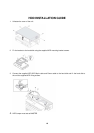

2. Rear Panel and Connections
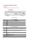
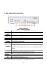
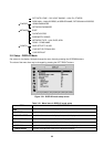
Figure 2.1. Rear Panel
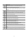
Table 2.1. Rear panel connections
Connection DESCRIPTION
n VIDEO IN
Four connectors for video input. Connect camera output to Video-in (NTSC/PAL)
o AUDIO IN
Four connectors for audio input.
p AUDIO OUT
One connector for audio output.
q VIDEO OUT
Composite video output in NTSC or PAL format
r RS-232
For engineering use only
s VGA
Connector for VGA monitor
t ETHERNET
RJ45 connector for LAN connection
u RS-485/422
For camera control use
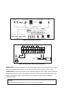
v SENSOR IN
Connector for sensor device connection. 4 sensors can be connected to the equipment
sensor 1, 2, 3, 4 are dedicated to Video channel 1, 2, 3, 4, respectively. Either normal
open (NO) or normal close (NC) sensor can be selected for each sensor. Simple On/Off
switching.
w ALARM OUT
Connector for alarm device connection.
Provides simple On/Off switching using relay. 0.5A/125V, 1A/30V
DC INPUT
Apply 12V DC using the DC adaptor supplied with the equipment.
SWITCHES
PAL
Set to ON position when video is PAL
VGA
Set to ON position when VGA monitor is used.
* Refer to the detail setting of video switch on Page 7 “Video Signal Select / Setting”.
18