


8
CHAP. 2 Function of Each Button
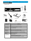
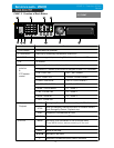
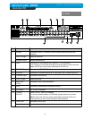
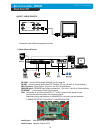
2-2. REAR
Name Function
1 RS 485 Connection with PTZ Camera or other external device using RS 485
interface
RELAY Output Relay out terminal
SENSOR Input Sensor input terminal
2 VGA Connection to VGA Monitor (CRT type or TFT LCD monitor)
Just in case you purchased DVR with VGA option board fixed on the main
board of DVR, you can connect VGA Monitor to DVR unit.
3 ETHERNET Connection to ETHERNET device
4 RS-232C Connection to external device as PC using RS-232C to control the DVR
5 CAMERA Input Connection with camera
6 LOOP Output Camera loop out
7 MONITOR
Output
Connection with Composite Monitor
8 SPOT Connection with additional composite monitor
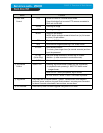
9 DC Power DC 12V 6.67A Adaptor
10 POWER
SWITCH
Power ON/OFF switch for adapters
To avoid accidental deletion of HDD data, please make sure to press
MENU button and enter into setup menu before powering off the unit.
This takes the unit out of record mode for safe shutdown.
11 Audio Input Microphone Input (4ch)
Audio Output Speaker Output (1ch)