


8 9
WARNING
TOOL ASSEMBLY
To reduce the risk of injury, always
unplug tool before attaching or
removing accessories or making
adjustments. Use only specifi cally
recommended accessories. Others
may be hazardous.
Assembly Order
To avoid injury or damage to the tool, follow
the order of sections in "Tool Assembly".
Set up the tool in the following order of
sections:
1. Setting up the Stand
2. Installing the Counterbalance
3. Mounting the Saw Motor
4. Installing Blades
5. Adjusting the Rulers
6. Installing the Blade Guard
7. Installing the Cord Keeper
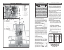
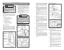
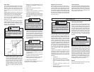
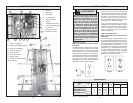
Setting up the Stand
Use at least two people to remove pack-
aging and set up the stand. One person
should hold the stand in an upright position
while the other removes the packaging and
sets the folding stand to make the tool free-
standing.
1. While having another person hold the
stand in the upright position, stand
behind the tool. Remove the locking
pin from the folded locking pin position
with one hand while holding the stand
base with your other hand so it does not
unfold onto your feet.
2. Unfold the stand slowly until the hole in
the sliding center bar is aligned with the
hole in the center bar.
3. Insert the locking pin through the holes
and lock it securely.
Sliding
center bar
Folded locking
pin position
Locking pin
Center bar
Unfolded locking
pin position
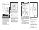
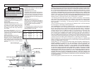
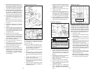
Installing the Counterbalance
Fig. 1
Fig. 2
Fig. 3
Counterbalance
Counterbalance
cable
Nut
Washer
Carriage
bolt
Cable
clip
Counterbalance
cable
Carriage
bolt
Cable clip tabs
Nut
Stand base
WARNING
To reduce the risk of injury or
damage to components, do not at-
tempt to disassemble or repair the
counterbalance. Do not pull on the
counterbalance cable. The cable
is under strong spring force. Unit
must be properly assembled before
removing cable clip.
1. Remove the (2) 1/4 - 20 nuts, (2) wash-
ers and (2) 1/4"-20 x 5/8" carriage bolts
from the counterbalance. Leave the nut
and bolt on the counterbalance cable in
place.
2. Remove the end of the cable from the
inside of the counterbalance. The coun-
terbalance must be installed off-center
to the right (while facing the saw from
the front): holes are cut into the top of
the tool frame.
3. Secure the counterbalance to the tool
using (2) carriage bolts, (2) washers,
and (2) nuts.
NOTE: The carriage bolts are installed
from the bottom up. Tighten nuts se-
curely.
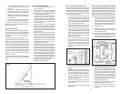
4. Hold the saw carriage securely while
loosening the carriage lock.
5. Raise the saw carriage until the oval
hole in the saw carriage aligns with the
eye hole in the counterbalance cable,
making sure the cable is behind the saw
carriage.
6. Tighten the carriage lock.
7. Remove the nut from the carriage bolt
and insert the bolt through the hole in
the saw carriage and the eye hole in
the counterbalance cable. Thread the
nut onto the bolt and tighten securely.
8. Bend the cable clip tabs down by
hand.
9. Loosen the carriage lock and lower the
saw carriage until the cable clip is fully
exposed.
10. Tighten the carriage lock.
11. Remove the cable clip from the counter-
balance cable and save it for future use
(i.e., If you remove the counterbalance
in the future, you will need the cable clip
to support the tension in the counterbal-
ance.)
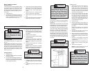
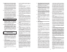
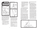
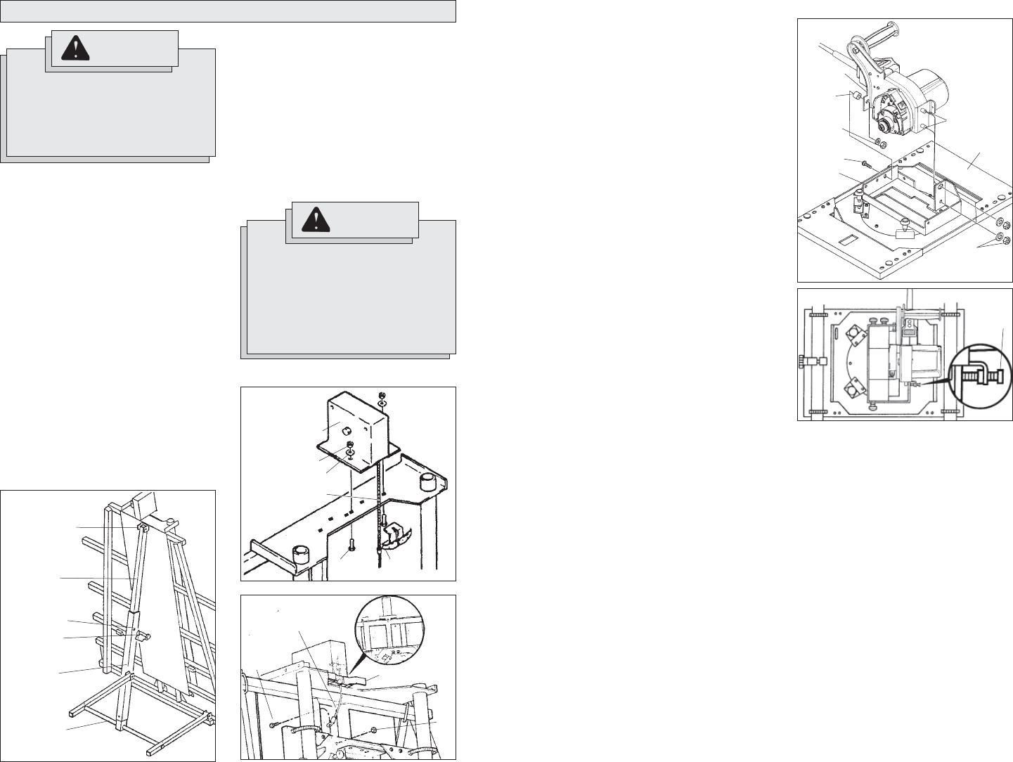
Mounting the Saw Motor
The motor is shipped with (3) washers, (3)
nuts, (1) spacer, and (1) bolt. Remove these
items to mount the saw.
1. Loosen the carriage lock and lower
the saw carriage to a comfortable work
height.
2. Tighten the carriage lock securely.
3. Mount the motor to the saw carriage by
inserting the studs on the saw motor
through the holes in the saw carriage
(Fig. 4).
4. Install washers and nuts. Hand-tighten
only.
5. Align the hole in the bracket that extends
from the saw handle with the hole on the
saw carriage.
6. Place the spacer between the bracket
on the carriage and bracket on the saw
handle.
7. Insert the bolt through the saw handle
bracket, through the spacer, and through
the hole in the carriage bracket.
8. Thread a nut onto the bolt. Hand-tighten
only.
Fig. 4
Bracket
Studs
9/16" Nuts
and washers
Spacer
7/16" Nut
and washer
Bolt
Bracket
Saw
carriage
Fig. 5
Leveling
screw