


12 13
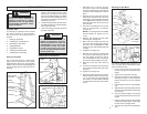
You are now ready to use your panel saw.
Refer to the "Operation" section for instruc-
tion on proper use.
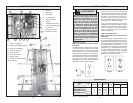
Panel Saw Alignment
The panel saw is aligned during manufactur-
ing to a tolerance of ±1/32". Field alignment
is required only if the unit is mishandled or
abused, or if motor or wheel replacement
is required.
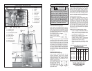
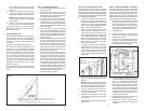
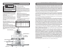
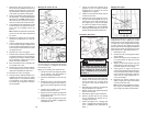
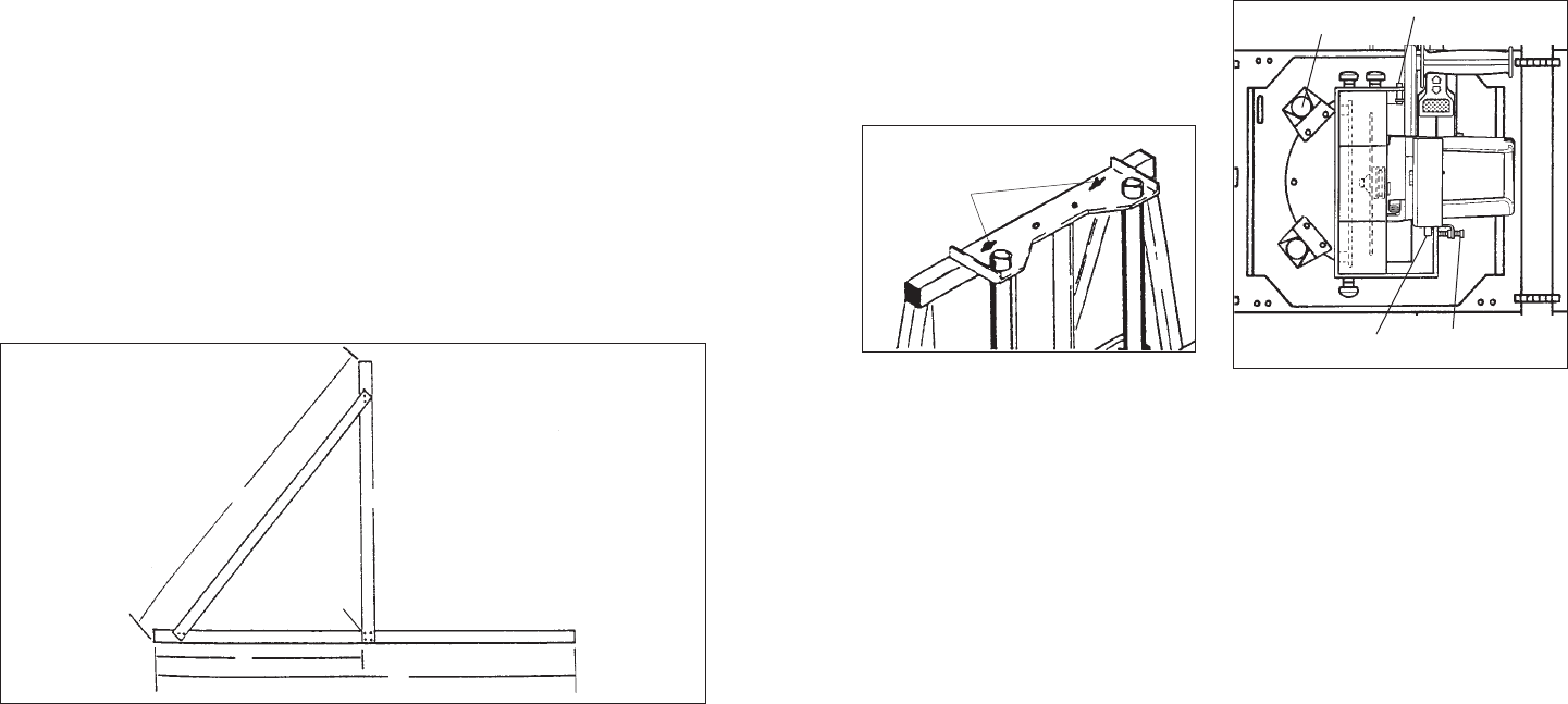
Construct a fi eld alignment tool (Fig. 11):
For maximum accuracy, manufacture a test
square (Fig. 11) to check the full movement
of the saw. Construct the square using one
6' metal ruler and two 4' metal rulers. Using
the 3'-4'-5' measurements assures square-
ness. Drill holes and attach the rulers with
pop rivets or small nuts and bolts. Use the
6' ruler to check squareness of the rollers
and the 4' ruler to check squareness of the
guide tubes. The tool also acts as a giant
square for layouts.
The alignment process consists of 4 steps
which must be performed in the following
order.
Step 1 - Adjusting the Rollers
1. To check roller alignment, remove exten-
sions (if present).
2. Retract the stand and lay the tool fl at
so the roller nuts are easily accessible.
With proper care, you may place the tool
on a table with guide tubes up.
3. The outermost rollers are stationary,
so adjust all other wheels to the two
outermost rollers. Lay the straight edge
of the fi eld alignment tool across the roll-
ers to verify alignment; all rollers should
contact the edge.
4. If a roller is "high" or "low" to the straight
edge, clamp a straight edge at least 5'
long to the top of the rollers so it lies fl at
on the frame and against the outermost
rollers, positioning the clamps above the
outermost roller.
5. With the straight edge clamped securely
in place, rotate each roller to be sure
that it neither jams nor has excessive
clearance to the straight edge. If a roller
runs "tight" or "loose" to the straight
edge, loosen the roller nut. Roller nuts
are torqued and require at least an 18"
braker bar to loosen them.
6. The rollers are mounted on an eccentric
hub. Turning a roller when the roller nut
is loose will cause the roller to change
its position. You may have to lift the front
roller carriage bar to rotate the eccentric
hub. Turn the roller until it contacts the
straight edge, being careful not to bend
or bow the straight edge when reposi-
tioning the wheel. Tighten the roller nut
securely, making sure the roller does not
change position. Repeat this process as
needed for the remaining rollers.
7. Reposition the tool upright.
Fig. 11
5'
4'
3'
6'
Line up on
36" mark
4' frame support
If the small end of the taper is on the
top, the stopper will not keep the cord
in place.
8. Loosen the carriage lock and allow the
saw carriage to return to the top of the
guide tubes. Tighten the carriage lock.
NOTE: If you discover there is too much
or not enough slack in the cord, readjust
as necessary.
9. Run the cord over the top of the panel
saw to get it out of the path of the saw.
Step 2 - Adjusting the Guide Tubes
If the saw does not cut at 90°, the guide
tubes may not be perpendicular to the rollers.
Unplug the saw cord before testing alignment
or making adjustments. Check the alignment
of the rollers before adjusting the guide tubes
(see "Adjusting the Rollers").
1. To check the guide tube alignment,
remove the upper guard assembly to
expose the blade. Mark a tooth to use as
a reference. If using a high-speed steel
blade, mark a tooth pointing toward the
edge of the fi eld alignment tool.
2. Clamp the fi eld alignment tool to the
roller assembly and pull the saw car-
riage down slowly so the marked refer-
ence tooth just touches the vertical edge
of the fi eld alignment tool. Continue to
pull the saw carriage down. If the blade
does not contact the square, or if the
blade binds on the square, the guide
tubes are not aligned.
3. To align the guide tubes, determine
which direction the top of the guide
should move. If the blade runs into
the square, the top guide goes to the
square. If the blade runs away from the
square, the top guide goes away from
the square.
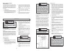
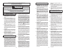
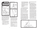
Fig. 12
Guide tube
bracket nuts
4. Loosen the guide tube bracket nuts
(Fig. 12), but do not remove the tube
bracket.
NOTE: Figure 12 shows the counterbal-
ance removed for illustration purposes.
It is not necessary to remove the coun-
terbalance to perform this procedure.
5. Using a deadblow mallet, strike the
bracket on the side and in the direction
the tubes need to move.
6. Recheck the squareness of the tubes
to the rollers repeating the procedure
as necessary.
7. Tighten the nuts on the upper guide tube
bracket nuts.
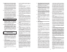
Factory-set
adjustment screw
5. Loosen (but do not remove) the two hex
head nuts holding the index pin brackets
(Fig. 13). If burn marks appear on the
left side of the workpiece, rotate the
saw slightly clockwise until the entire
face of the blade contacts the square.
If burn marks appear on the right side
of the workpiece, rotate the saw slightly
counterclockwise until the entire face of
the blade contacts the square. ONLY
make slight adjustments.
6. Securely tighten the two hex head nuts
holding the index pin brackets.
7. Plug in the tool and make another
sample cut. Repeat the procedure if
necessary.
Mounting nut
Fig. 13
Index Pin
Brackets
Mounting nut
Step 3 - Adjusting the Blade - Parallelism
The blade should be parallel to the guide
tubes, otherwise tail burning may occur and
the kerf will be wider than the set of the blade.
Make the following adjustments only if the
blade appears to be out of alignment. AL-
WAYS check for alignment of the rollers and
the guide tubes before adjusting the blade.
1. To check for blade parallelism, position
the saw carriage for a cross-cut and
make a sample cut. If the blade "heels",
burns marks on the cut, etc., check both
sides of the cut to determine which side
of the blade is causing the problem.
2. Unplug the tool.
3. Position the square on the rollers and
lower the saw carriage so the square
overhangs the blade.
4. Place the square against the blade. The
entire face of the blade should contact
the square. If it does not, then the blade
is not parallel to the workpiece.