


7 - 24
7 DATA LINK PROCEDURE
MELSEC-QnA
Continued from the previous page
End
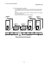
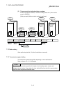
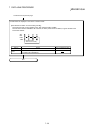
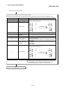
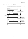
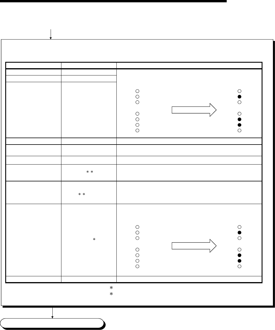
The test results are displayed on the "LEDs" of master module.
By switching the mode setting switch, the parameter content corresponding to each mode number is displayed on LED.
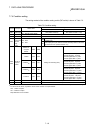
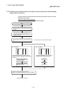
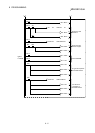
Mode setting switch Parameter item
Used LEDs and contents
0
1
2
Total number of stations
Number of linked modules
Number of retries
Tens digit: MST, S MST, LOCAL
Units digit: SW, M/S, PRM, TIME
3
4
(Unusable)
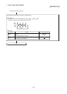
5
Reserved station
specification
Invalid station specification
SW (off: no specification, on: specification exists)
SW (off: no specification, on: specification exists)
6
SW: remote I/O station
M/S: remote device station
PRM: local station, standby master station, and intelligent device station
7
SW: 1 station
M/S: 2 stations
PRM: 3 stations
TIME: 4 stations
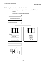
8
Tens digit: MST, S MST, LOCAL
Units digit: SW, M/S, PRM, TIME
9 to F
(Unusable)
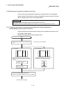
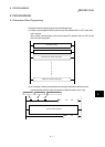
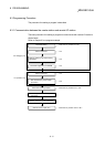
Station number
When 26
MST
S SMT
LOCAL
SW
M/S
PRM
TIME
· · · · · · 40
· · · · · · 20
· · · · · · 10
· · · · · · 8
· · · · · · 4
· · · · · · 2
· · · · · · 1
MST
S SMT
LOCAL
SW
M/S
PRM
TIME
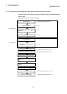
When 26
MST
S SMT
LOCAL
SW
M/S
PRM
TIME
· · · · · · 40
· · · · · · 20
· · · · · · 10
· · · · · · 8
· · · · · · 4
· · · · · · 2
· · · · · · 1
MST
S SMT
LOCAL
SW
M/S
PRM
TIME
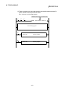
Station type
1
2
12
Number of occupied
stations
1
1: Set the module's station number by the station number setting switch.
2: For modules that occupy more than two stations, the same LED
details are displayed for the number of occupied stations.