


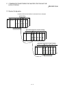
10 - 12
10 COMMUNICATION BETWEEN THE MASTER STATION AND THE
REMOTE DEVICE STATION
MELSEC-QnA
10.3 Performing the Data Link
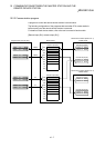
Turn on the power supply of the remote device station first, then the power supply of
the master station to start the data link.
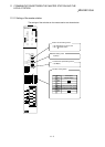
10.3.1 Confirming the operation by LED display
The following diagram shows the LED display status of the master station and the
remote I/O station when the data link is performed normally.
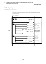
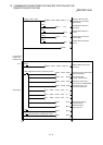
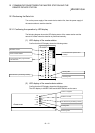
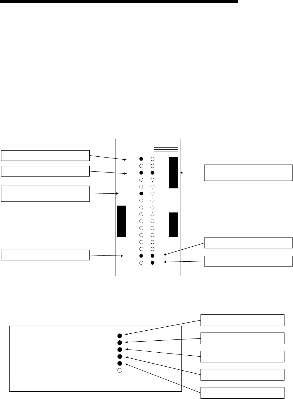
(1) LED display of the master station
Confirm that the LED display shows the following status:
AJ61QBT11
RUN 156K
ERR. 625K
MST 2.5M
S MST 5M
LOCAL 10M
CPU R/W
SW
M/S TEST
PRM S0
TIME S1
LINE S2
L RUN SD
L ERR. RD
B
R
A
T
E
T
E
S
T
E
R
R
O
R
Module is normal.
Set as a master station.
Communicating with programmable
controller CPU.
The data link is proceeding normally.
The transmission speed is set to
2.5Mbps.
Sending data.
Receiving data.
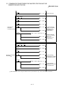
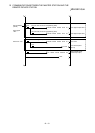
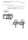
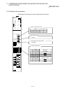
(2) LED display of the remote device station
Confirm that the LED display shows the following status:
The LED display in AJ65BT-64AD and AJ65BT-64DAV are the same.
PW
A
J65BT-64AD
RUN
L RUN
SD
RD
L ERR.
24VDC is supplied.
Module is normal.
The data link is proceeding normally.
Sending data.
Receiving data.