


Appendix A: Special Device List
187
FX3S Series Programmable Controllers
User's Manual - Hardware Edition
11
Built-in Analog
12
Output Wiring
13
Wiring for
Various Uses
14
Test Run,
Maintenance,
Troubleshooting
15
Other Extension
Units and
Options
16
Display Module
(FX
3S
-5DM)
17
Memory
Cassette
A
Special Devices
(M8000-, D8000-)
B
Instruction List
C
Discontinued
models
Appendix A-1 Special Auxiliary Relay (M8000 to M8511)
Appendix A: Special Device List
The device numbers and functions of the special auxiliary relays (indicated as "special M" in tables) and
special data registers (indicated as "special D" in tables) are shown below.
Note that functions of certain devices vary depending on the series of the PLC.
Do not use the undefined/blank special auxiliary relays and special data registers in the sequence program
since they are occupied by the CPU.
In addition, do not activate or write to the devices with brackets on the first letter such as [M]8000 or [D]8001
in the program.
For detailed explanation, refer to the Programming Manual.
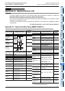
Appendix A-1 Special Auxiliary Relay (M8000 to M8511)
*1. Cleared when PLC switches from RUN to STOP.
*2. Executed at END instruction.
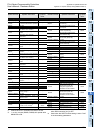
Number and name Operation and function
Correspond-
ing special
device
PLC status
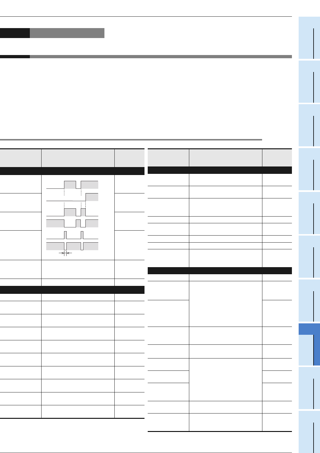
[M]8000
RUN monitor
NO contact
-
[M]8001
RUN monitor
NC contact
-
[M]8002
Initial pulse
NO contact
-
[M]8003
Initial pulse
NC contact
-
[M]8004
Error occurrence
ON when either M8061, M8062,
M8064, M8065, M8066, or M8067 is
ON.
D8004
[M]8005 to [M]8009 Not used -
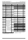
Clock
[M]8010 Not used -
[M]8011
10 ms clock pulse
ON and OFF in 10 ms cycle
(ON: 5 ms, OFF: 5 ms)
-
[M]8012
100 ms clock pulse
ON and OFF in 100 ms cycle
(ON: 50 ms, OFF: 50 ms)
-
[M]8013
1 sec clock pulse
ON and OFF in 1 sec cycle
(ON: 500 ms, OFF: 500 ms)
-
[M]8014
1 min clock pulse
ON and OFF in 1 min cycle
(ON: 30 sec, OFF: 30 sec)
-
M 8015
Clock stop and preset
For real time clock
-
M 8016
Time read display is stopped
For real time clock
-
M 8017
±30 seconds correction
For real time clock
-
[M]8018
Installation detection (Always ON)
For real time clock
-
M 8019
Real time clock (RTC) error
For real time clock
-
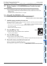
1 scan time
RUN
input
M8000
M8001
M8002
M8003
M8061
Error occurrence
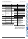
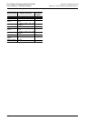
Number and name Operation and function
Correspond-
ing special
device
Flag
[M]8020
Zero
ON when the result of addition/
subtraction is 0.
-
[M]8021
Borrow
ON when the result of subtraction is
less than the min. negative number.
-
M 8022
Carry
ON when 'carry' occurs as a result
of addition or when an overflow
occurs as a result of shift operation.
-
[M]8023 Not used -
M 8024
*1
BMOV instruction (FNC 15)
direction specification
-
[M]8025 to [M]8027 Not used -
M 8028 100 ms/10 ms timer changeover -
[M]8029
Instruction
execution complete
ON when operation such as DSW
instruction (FNC 72) is completed.
-
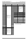
PLC mode
M 8030 Not used -
M 8031
*2
Non-latch memory
all clear
If this special auxiliary relay is
activated, the ON/OFF image
memory of Y, M, S, T, and C, and
present values of T, C, D and
special data registers are cleared to
zero.
However, file registers (D) in
program memory.
-
M 8032
*2
Latch memory all
clear
-
M 8033
Memory hold STOP
When PLC is switched from RUN to
STOP, image memory and data
memory are retained.
-
M 8034
*2
All outputs disable
All external output contacts of PLC
are turned OFF.
-
M 8035
Forced RUN mode
Refer to Programming Manual for
details.
-
M 8036
Forced RUN signal
-
M 8037
Forced STOP
signal
-
[M]8038
Parameter setting
Communication parameter setting
flag (for N:N network setting)
D8176 to
D8180
M 8039
Constant scan
mode
When M8039 is ON, PLC waits until
scan time specified in D8039 and
then executes cyclic operation.
D8039