


18 Chapter 1. Television Overview
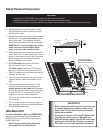
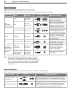
Back and Side Panels, continued
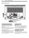
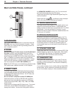
7. PC-DVI AUDIO
Use the
PC-DVI AUDIO
jacks in conjunction with the
PC-DVI
video input from a personal computer. These
jacks allow you to send left and right analog audio from
your computer to the TV.
8. PC-DVI
Do not connect a TV video source to the PC-DVI input.
PC-DVI
is a DVI-I input compatible with both DVI-A
(analog) and DVI-D (digital) signals. Connect your per-
sonal computer’s HDMI, DVI, or VGA video output to this
jack. An adapter or converter cable may be required.
Please see Appendix B for signal compatibility. To hear
audio from the computer, connect analog audio cables
from the computer to the
PC-DVI AUDIO
jacks.
Note: The PC-DVI input is not intended for standard video
from cable boxes, satellite receivers, or DVD players.
9. HDMI™ 1 and 2
The HDMI (High Definition Multimedia Interface) supports
uncompressed standard and high-definition digital video
formats and PCM digital audio format. For PC video, use
the
PC-DVI
input instead.
Do not connect a computer to either TV HDMI jack.
Use these inputs to connect to EIA/CEA-861 compliant
devices such as a high-definition receiver or DVD player.
These inputs support 480i, 480p, 720p, 1080i, and 1080p
video formats.
These inputs can also accept DVI video inputs. To connect
a DVI input, use an HDMI-to-DVI adapter or cable plus
analog audio cables. Connect the analog audio cables to
the
HDMI/DVI AUDIO
inputs on the TV to receive left
and right stereo audio from your DVI device.
These inputs are HDCP (High-Bandwidth Digital Copy Pro
-
tection) compliant.
These inputs are
certified for proper interoper-
ability with other products certified by Simplay™.
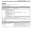
10. DIGITAL AUDIO OUTPUT
This output sends Dolby Digital or PCM digital audio to your
digital A/V surround sound receiver. Analog audio from
analog channels and devices is converted by the TV to PCM
digital audio. If you have a digital A/V receiver, in most
cases this is the only audio connection needed between the
TV and your A/V receiver.
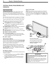
11. IR Emitter NetCommand®
IR Emitters connected to this jack are used by the TV’s
NetCommand system to control external IR remote con-
trolled analog devices such as cable boxes, VCRs, DVDs,
satellite receivers and audio receivers. This system also
coordinates with the TV Guide On Screen® system to
control cable boxes and to activate the record feature of
your VCR.
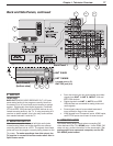
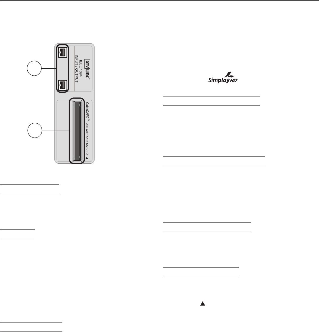
12. DTVLINK™/IEEE 1394
These jacks allow the TV to connect to external IEEE 1394
digital products by means of a single cable. See chapter
6, “Using IEEE 1394 Devices” for detailed information
regarding IEEE 1394 connections and recording.
13. CableCARD™ Slot
The CableCARD access card from your cable TV service
provider is inserted into this slot. When inserting, ensure
that the top of the card faces in the direction indicated by
CARD TOP
.
If your cable company is not currently offering CableCARD
access cards, use the cable box provided and authorized
by your local cable company to view scrambled channels.
12
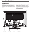
Side Panel
13