


20
20
Part II: Installation
Connecting an Audio/Video Surround Sound Receiver
IN IN IN IN IN IN IN INOUT OUT OUT OUT
AUX CD TAPE 1 TAPE 2 VCR 1 VCR 2 TV
DVD
MONITOR VCR 1 VCR 2 TV DVD
MONITOR VCR 1 VCR 2 TV DVD
OUT
OUT
IN
IN
IN
IN
IN
IN
IN
IN
OUT OUT
OUT OUT
CENTER
SUB
WOOFER
FRONTSUR.
REC
SOURCE
LINE OUT
PRE OUT
SURROUND
SPEAKERS (6Ω MIN.
)
FRONT
SPEAKERS-A (6Ω MIN.)
FRONT
SPEAKERS-B (6Ω MIN.)
CENTER
(6Ω MIN.
)
L
L
L
L
L
R
R
R
R
R
THIS DEVICE COMPLIES WITH PART 15 OF THE
FCC RULES. OPERATION IS SUBJECT TO THE
FOLLOWING TWO CONDITIONS: (1) THIS DEVICE
MAY NOT CAUSE HARMFUL INTERFERENCE AND
(2) THIS DEVICE MUST ACCEPT ANY INTERFERENCE
RECEIVED, INCLUDING INTERFERENCE THAT MAY
CAUSE UNDESIRED OPERATION.
MANUFACTURED UNDER LICENSE FROM DOLBY LABORATORIES LICENSING
CORPORATION. "DOLBY", "PRO LOGIC" AND THE DOUBLE-D SYMBOL ARE
TRADEMARKS OF DOLBY LABORATORIES CORPORATION.
COPYRIGHT 1992 DOLBY LABORATORIES, INC. ALL RIGHTS
RESERVED
INPUT-1
(OPTICAL)
INPUT-2
(COAXIAL)
INPUT-3
(COAXIAL)
DIGITAL AUDIO
SWITCHED
UNSWITCHED
AC 120V - 60Hz
TOTAL 100W, 0.9A MAX
AC OUTLETS
MITSUBISHI
AUDIO/VIDEO RECEIVER
MODEL M-VR1000
POWER SUPPLY
POWER CONSUMPTION
120V-60Hz
552W, 732VA
DISTRIBUTED BY
MITSUBISHI CONSUMER ELECTRONICS AMERICA
INC.
6100 ATLANTIC BLVD MADE IN
JAPAN
NORCROSS, GA 30071-1305 FABRIQUE EN
JAPAN
!
AVIS
RISQUE DE CHOC ELECTRONQUE
NE PAS ENLEVER
RISK OF ELECTRIC SHOCK
DO NOT OPEN
ANTENNA
75Ω
300Ω
FM
AM
GND
ATUO
STANDBY
ON
OFF
σ
τ
S-VIDEO
VIDEO
AUDIO
WARNING
DIGITAL
AUDIO
OUTPUT
IR
EMITTER
HOME
THEATER
CONTROL
MEMORY
CARD
IEEE
-1394
INPUT/
OUTPUT
ANT-DTV
INPUT
OUT
PUT
1 2 3 4
MONI
TOR
PI
P
S-VIDEO
VIDEO
AUDIO-
LEFT
(MONO)
AUDIO-
LEFT
(MONO)
AUDIO-
RIGHT
AUDIO-
RIGHT
VGA
640 X 480,60Hz
1(YPrPb) 2 (YPrPb)
COMPONENT 480i/480p
DTV
(YPrPb/GRBHV)
480i/480p/1080i
HIGH RESOLUTION INPUT
Y
G
P
r
R
P
b
B
H
V
IR EMITTER-REPEATER
ANT-A
LOOP
OUT
ANT-B
1
Attach only one
cable type
2
2
3
3
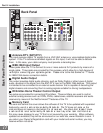
TV Rear Panel
A/V Receiver Rear Panel
Use only if connecting a Dolby Digital A/V Receiver
Ferrite end
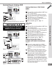
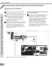
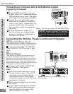
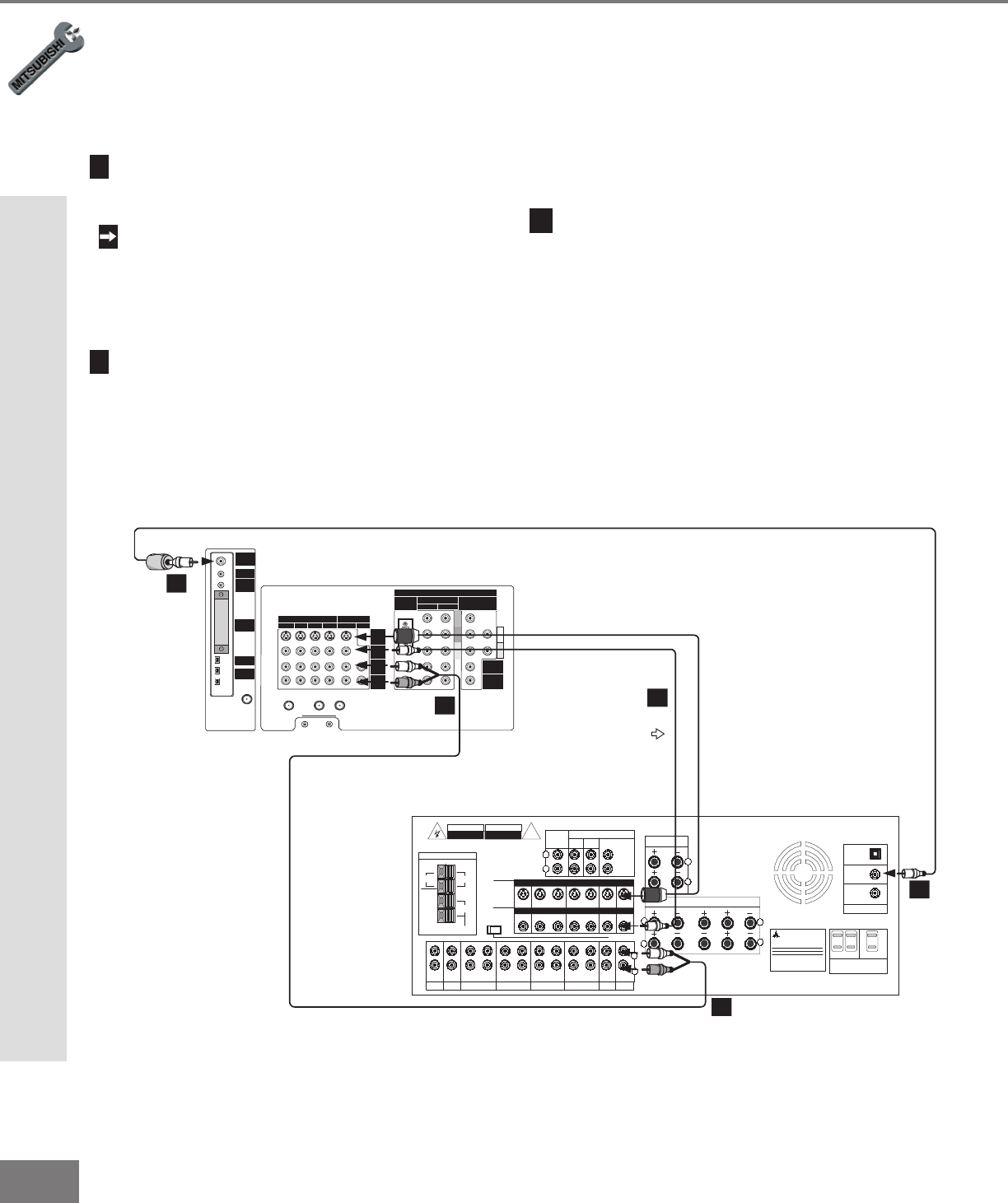
Connecting an A/V Receiver
(Figure 1)
1
Connect a video cable from Monitor VIDEO
OUTPUT on the back of the TV to the TV
VIDEO INPUT on the back of the A/V Receiver.
If you have connected a S-VHS VCR to the
A/V Receiver, then follow the same video
connection using the S-Video cable and
terminals on the TV and A/V Receiver (in
place of the VIDEO cable).
2
Connect a set of audio cables from the Monitor
AUDIO OUTPUT on the back of the TV to the
TV AUDIO INPUT on the back of the A/V
Receiver. The red cable connects to the R
(right) channel and the white cable connects
to the L (left) channel.
Figure 1. Connecting an Audio/Video Receiver
If connecting a digital A/V Receiver with Dolby
Digital
TM
surround sound.
3
Connect one end of the digital audio cable sup-
plied with the TV to the DIGITAL AUDIO
OUTPUT on the back of the TV (connect
the end of the cable with the ferrite or plastic
cylinder). Connect the other end to the
COAXIAL DIGITAL INPUT on the back
of the A/V Receiver. Check the Owner’s
Guide for the A/V Receiver for information
concerning the use of the digital input and
switching between the digital sound and analog
stereo sound from the TV.
Connecting an Audio/Video Surround Sound Receiver