


19
19
Part II: Installation
Do not display the same stationary images on the screen for more that 15%
of your total TV viewing in one week. Examples of stationary images are
letterbox top/bottom bars from DVD or other video sources, side bars when showing standard
TV pictures on widescreen TV’s, stock market reports, video game patterns, station logos, web
sites, or stationary computer images. Such patterns can unevenly age the picture tubes causing
permanent damage to the TV. Please see pages 23 and 62 for a detailed explanation.
WARNING:
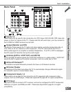
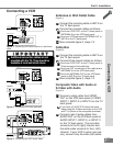
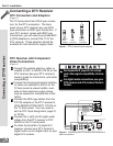
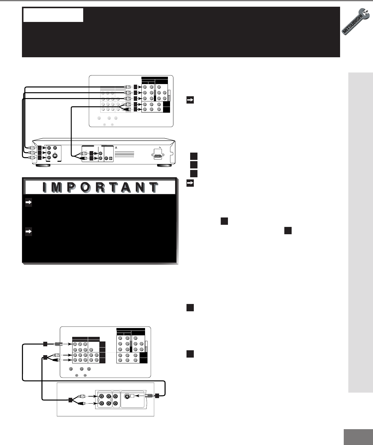
Connecting a DVD Player
DVD Player with Component Video
(Figure 1)
Connect the Component Video cables
from Y/Cr/Cb or Y/Pr/Pb VIDEO OUT
on the back of the DVD player to COM-
PONENT-1 or COMPONENT-2 on the
TV back panel, matching the correct
components:
1
Y to Y
2
Cr or Pr to Pr
3
Cb or Pb to Pb
Connect a set of audio cables from
AUDIO OUT on the back of the DVD
player to COMPONENT AUDIO Input 1
or 2 on the TV back panel. The red
cable
4
connects to the R (right) chan-
nel, and the white cable
5
connects to
the L (left) channel.
See Appendix B, page 65, for compo-
nent video signal compatibility informa-
tion.
For digital audio connections, see your
DVD and A/V receiver Owner’s Guides.
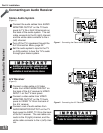
Connecting a DVD Player or S-Video Device
Y
G
Pb
B
Pr
R
V
H
HIGH RESOLUTION INPUT
INPUT
3 PIP
S-VIDEO
COMPONENT
480i /480p
1 (YPrPb)
2 (YPrPb)
DTV (YPrPb/GRBHV)
480i /480p /1080i
VIDEO
MONITOR
ACTIVE A/V
NETWORK
IR - HOME
THEATER
21
OUTPUT
AUDIO-
LEFT/
(MONO)
AUDIO-
RIGHT
AUDIO-
LEFT/
(MONO)
AUDIO-
RIGHT
ANT-BLOOP OUTANT-A
VIDEO
S
Y
CB
CR
VIDEO OUT
BITSTREAM/PCM5.1 CH SURROUND 2CH
L
R
CENTER
SUBWOOFER SURROUND FRONT COAXIAL OPTICAL
AUDIO OUT
AC IN
MITSUBISHI
DVD PLAYER
MODEL
DD-5000
POWER SUPPLY 120V~ 60Hz
POWER CONSUMPTION 20W
MITSUBISHI DIGITAL ELECTRONICS
DISTRIBUTED BY
9351 JERONIMO ROAD
IRVINE, CA 92618
MADE IN JAPAN
AMERICA, INC.
SERIAL NO.
MANUFACTURED
White
Red
White
Red
DVD back panel
2
1
1
3
5
5
4
4
2
3
TV back panel
Figure 1. Connecting the DVD player.
Y
G
Pb
B
Pr
R
V
H
HIGH RESOLUTION INPUT
INPUT
3 PIP
S-VIDEO
COMPONENT
480i /480p
1 (YPrPb)
2 (YPrPb)
DTV (YPrPb/GRBHV)
480i /480p /1080i
VIDEO
MONITOR
ACTIVE A/V
NETWORK
IR - HOME
THEATER
21
OUTPUT
AUDIO-
LEFT/
(MONO)
AUDIO-
RIGHT
AUDIO-
LEFT/
(MONO)
AUDIO-
RIGHT
ANT-BLOOP OUTANT-A
AUDIO OUT
AUDIO IN
VIDEO OUT
(Y/C)
L
R
L
R
1
2
2
1
1
2
TV back panel
Any S-Video Device
White
Red
White
Red
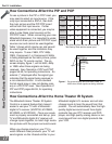
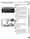
Figure 2. Connecting any S-Video Device.
Other S-Video Device
(Figure 2)
1
Connect a S-Video cable from VIDEO
OUT on the device back panel to VIDEO
INPUT-1, INPUT-2, or INPUT-3 on the
TV back panel.
2
Connect a set of audio cables from
AUDIO OUT on the device back panel
to AUDIO INPUT-1 or INPUT-2 on the
TV back panel. The red cable connects
to the R (right) channel and the white
cable connects to the L (left) channel. If
your DVD is mono (non-stereo), connect
only the white (left) cable.
Connecting a S-Video Device