


22
22
Y
G
Pb
B
Pr
R
V
H
HIGH RESOLUTION INPUT
INPUT
3 PIP
S-VIDEO
COMPONENT
480i /480p
1 (YPrPb)
2 (YPrPb)
DTV (YPrPb/GRBHV)
480i /480p /1080i
VIDEO
MONITOR
ACTIVE A/V
NETWORK
IR - HOME
THEATER
21
OUTPUT
AUDIO-
LEFT/
(MONO)
AUDIO-
RIGHT
AUDIO-
LEFT/
(MONO)
AUDIO-
RIGHT
ANT-BLOOP OUTANT-A
TV back panel
1
Mitsubishi Component back panel section
PREOUT
A/V NETWORK
INPUT
REAR CENTER
SUB
WOOFER
IN OUT
L
R
L
R
Ferrite
Core
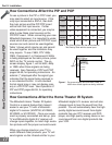
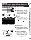
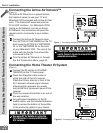
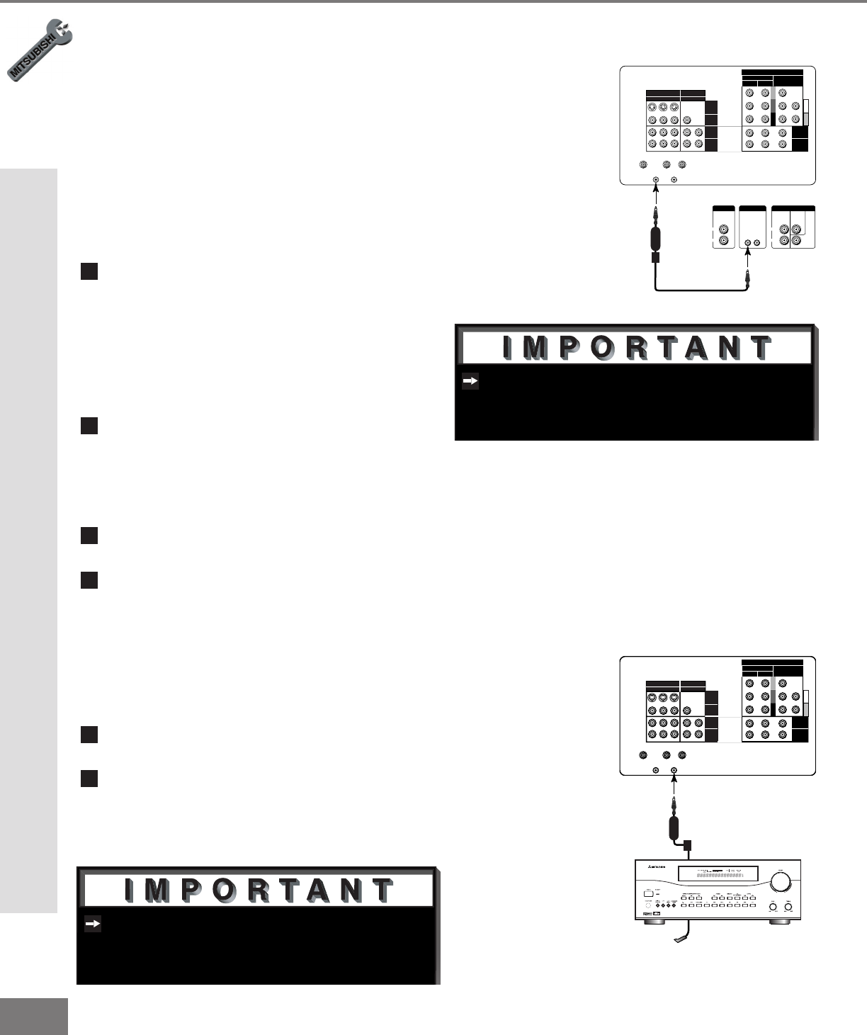
Figure 1. Connecting the Active A/V Network.
Y
G
Pb
B
Pr
R
V
H
HIGH RESOLUTION INPUT
INPUT
3 PIP
S-VIDEO
COMPONENT
480i /480p
1 (YPrPb)
2 (YPrPb)
DTV
(YPrPb/GRBHV)
480i /480p /1080i
VIDEO
MONITOR
ACTIVE A/V
NETWORK
IR - HOME
THEATER
21
OUTPUT
AUDIO-
LEFT/
(MONO)
AUDIO-
RIGHT
AUDIO-
LEFT/
(MONO)
AUDIO-
RIGHT
ANT-BLOOP OUTANT-A
TV back panel
Mitsubishi
A/V Receiver
1
D IGI TA L
SU R R O U N D
S
CH
Ferrite
Core
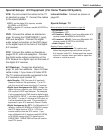
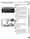
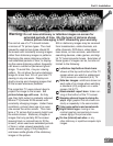
Figure 2. Connecting the Home Theater IR System.
Check your added Mitsubishi compo-
nent’s Owner’s Guide to ensure the best
possible connection.
See page 57 for details on using the
TV’s IR emitter to control a Mitsubishi
A/V receiver.
Part II: Installation
Connecting the Active AV Network™
(Figure 1)
The Active AV Network is a special feature
that makes it easier to use your TV and
Mitsubishi VCR equipped with Active AV Net-
work. This feature will automate common
TV-to-VCR functions. For Mitsubishi VCRs
having an AV Network, but not an Active
AV Network, this connection will pass the
remote control commands to your hidden
VCR.
1
Connect the Active AV Network cable
from ACTIVE A/V NETWORK on the TV
back panel to ACTIVE A/V NETWORK
IN, or A/V NETWORK IN on the back
of your Mitsubishi VCR. The end of the
cable with the Ferrite Core should be
connected to the TV
2
Turn the Active AV Network on through
the A/V Connection Menu, page 32.
1
Connect the IR emitter to IR HOME
THEATER on the TV back panel.
2
Place the IR emitter cable under or
along the side of the A/V receiver.
Place the IR lens directly in front of the
A/V receiver’s infrared signal receiver.
Infrared signal receivers are usually
behind the front translucent panel of the
receiver.
3
Place the unused transmitter in an out-of-
the-way location.
4
For permanent installation of the IR
emitter cable, use the included adhesive
tape to secure the bottom of the emitter
to the anchoring object of your choice.
Connecting the Home Theater IR System
(Figure 2)
Connecting the Active A/V Network & Home Theater IR System