14
15
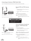
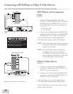
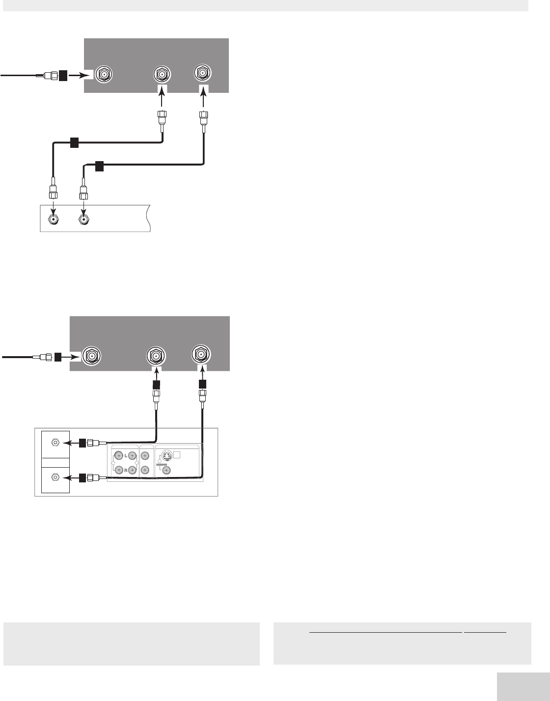
Figure 3. Connecting the cable box that does not have
audio or video outputs.
Note: See page 5 for Outdoor Antenna Grounding
Cable Box
(Figure 3)
1. Connect the incoming cable to ANT-A on the
TV back panel.
Connect two coaxial cables as follows:
2. One from LOOP-OUT on the TV back panel to IN
on the cable box back panel.
3. One from OUT on the cable box back panel to
ANT-B on the TV back panel.
NOTE: If your cable box has separate audio/video
outputs, please see Composite Video with
Audio or S-Video with Audio, page 16
(Figure 6).
Note: If you have a digital cable box, refer to your
Digital Cable Box owner’s guide for instructions on
optimal connections to this TV.
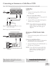
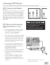
Antenna or Wall Outlet Cable
(Figure 4)
1.
Connect the incoming cable to ANT-A on the TV
back panel.
Connect two coaxial cables as follows:
2. One from LOOP-OUT on the TV back panel to
ANTENNA IN on the VCR back panel.
3. One from VCR back panel ANTENNA OUT to
ANT-B on the TV back panel.
NOTE: If your cable box has separate audio/video
outputs, please see Composite Video with
Audio or S-Video with Audio, page 16
(Figure 6).
Note: The TV back panel and connections shown here are for reference only and may vary by model.
�
Figure 4. Connecting the VCR with antennas or wall
outlet table.
Connecting an Antenna to a Cable Box or VCR
Note: For models WS-, WS- and WS-,
when the Energy Mode is set to Low, the VCR may not
record programs when the TV is off.


