


16
17
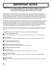
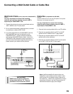
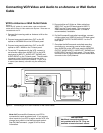
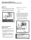
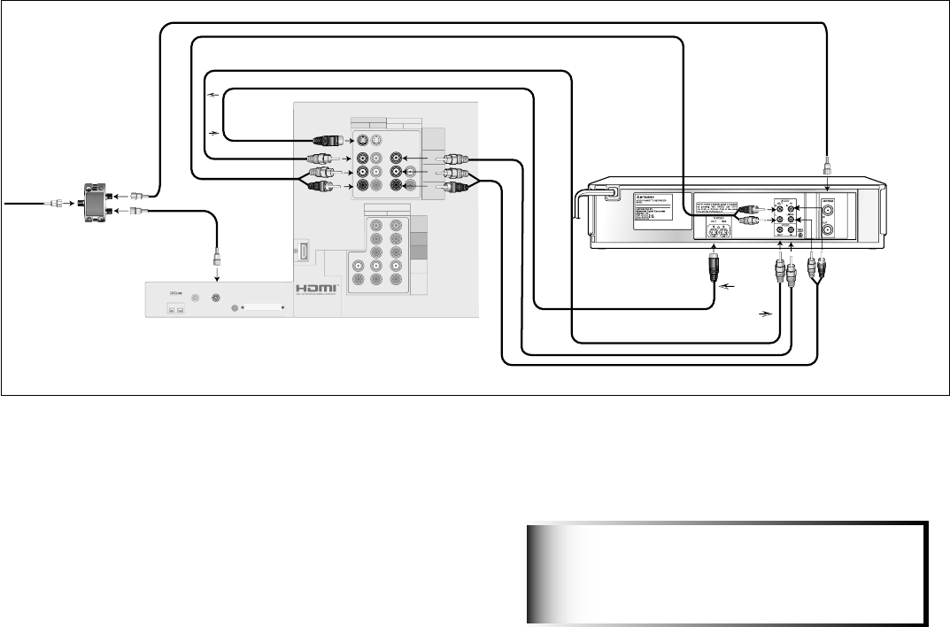
Connecting VCR Video and Audio to an Antenna or Wall Outlet
Cable
VCR to Antenna or Wall Outlet Cable
Figure 5
A two-way RF splitter, 3 coaxial cables, right and left audio
cables and S-Video or Video cables are required. These are not
included with the TV.
1. Connect the incoming cable or Antenna to IN on the
RF splitter.
2. Connect one coaxial cable from OUT on the RF
splitter to ANTENNA IN on the VCR back panel.
3. Connect one coaxial cable from OUT on the RF
splitter to ANT-1 MAIN on the TV back panel.
4. To use the TV speakers with the VCR, connect a
set of audio cables from AUDIO OUT on the VCR
back panel to INPUT 1 AUDIO-LEFT (MONO) and
AUDIO-RIGHT on the TV back panel. The red cable
connects to the R (right) channel and the white
cable connects to the L (left) channel. If your VCR
is mono (non-stereo), connect only the white (left)
cable.
TUBE
R
DIGITAL
IEEE1394
INPUT/OUTPUT
AUDIO
ANT-2
AUX
ANT-1
MAIN
CableCARD
TM
SLOT
– (DTV/CABLE /VHF/UHF) –
S-VIDEO
VIDEO
AUDIO-
LEFT/
(MONO)
AUDIO-
RIGHT
INPUT MONITOR OUTPUT
AUDIO 21 2
COMPONENT
YPbPr (480i/480p/1080i)
21
Y
Pb
Pr
AUDIO-
LEFT/
(MONO)
AUDIO-
RIGHT
DVI
Digital Video
Digital Audio
Analog Audio
S-Video
recommended
if available
Attach
only
one
cable
type
TV back panel
4.
– (DTV/CABLE /VHF/UHF) –
5.
S-VIDEO
VIDEO
AUDIO-
LEFT/
(MONO)
AUDIO-
RIGHT
INPUT
1 2
ANT-1
MAIN
MONITOR OUTPUT
AUDIO/VIDEO 1
7.
3.
6.
7.
HS-U748
VCR back panel
If your VCR has a video channel
or RF ON/OFF switch, set it to OFF.
5.
4.
5.
6.
2.
S-Video
recommended
if available
White
Red
White
Red
White
Red
W
h
i
t
e
R
e
d
Attach
only
one
cable
type
IN
OUT
OUT
TWO WAYSPLITTER
Incoming Cable
1.
2.
3.
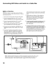
Note:NetCommand® will assume your VCR is
connected to inputs as shown here. If you use any
other inputs for your VCR or add a second VCR, this
change must match in the NetCommand system.
See Edit NetCommand... pages 35-42 for more
information.
Figure 5. Connecting a VCR to an Antenna or Wall Outlet Cable
5. Connect either an S-Video or Video cable from
VIDEO OUT on the VCR back panel to INPUT 1
VIDEO on the TV back panel. Only one type of
video cable should be connected. S-Video is
recommended, if available.
6. For NetCommand® controlled recordings, connect
a Video cable from VIDEO IN on the VCR back panel
to MONITOR OUTPUT AUDIO/VIDEO 1 on the TV
back panel.
7. Complete the NetCommand controlled recording
connection by connecting a set of audio cables
from AUDIO IN on the VCR back panel to MONITOR
OUTPUT AUDIO/VIDEO 1 AUDIO-LEFT (MONO) and
AUDIO-RIGHT on the TV back panel. The red cable
connects to the R (right) channel and the white cable
connects to the L (left) channel.
Additional connection cables are
not provided with the TV. They are
available at most electronic stores.
IMPORTANT