


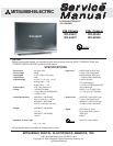


MODEL: WD-52527 / WD-52528 / WD-62527 / WD-62528
Page 3
INTRODUCTION ................................................................................................................................5
PRODUCT SAFETY NOTICE ...........................................................................................................5
SAFETY PRECAUTIONS .................................................................................................................6
DISASSEMBLY ................................................................................................................................. 7
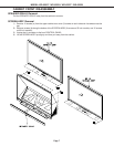
Front Cabinet Components ............................................................................................................. 7
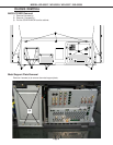
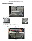
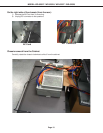
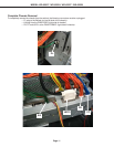
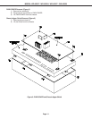
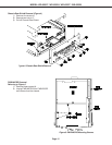
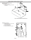
Chassis Removal ............................................................................................................................ 8
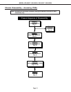
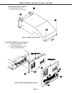
Chassis Disassembly / Accessing PWBs..................................................................................... 12
Light Engine Replacement ............................................................................................................ 17
SERVICING THE LENTICULAR SCREEN AND FRESNEL LENS ..................................................... 22
Removal of the Lenticular Screen and Fresnel Lens ...................................................................... 22
Installation of the Lenticular Screen and Fresnel Lens................................................................... 24
ADJUSTMENTS ............................................................................................................................... 25
Option Menu & Defaults ................................................................................................................ 25
LED Indicator Diagnostics............................................................................................................. 26
Error Codes Operational Check..................................................................................................... 27
Remote Operational Mode ............................................................................................................ 28
Service Adjustment Mode ............................................................................................................. 28
Service Adjustment Mode Operation .................................................................................... 28
Transferring data .................................................................................................................. 29
Light Engine Adjustment ............................................................................................................... 30
Test Signal activation ........................................................................................................... 30
Preliminary .......................................................................................................................... 30
Trapezodial Distortion Adjustment ........................................................................................ 31
Rotation Adjustment.............................................................................................................31
Hortizontal & Vertical Position.............................................................................................. 32
TROUBLESHOOTING .................................................................................................................. 33
MICRO / TERMINAL PWBs ................................................................................................. 33
POWER-PWB ..................................................................................................................... 34
OPTICAL ENGINE ............................................................................................................... 35
Protect Lines ....................................................................................................................... 36
USING LEAD FREE SOLDER .......................................................................................................... 37
CHIP PARTS REPLACEMENT ......................................................................................................... 38
REPLACEMENT PARTS ..................................................................................................................39
Parts Ordering .............................................................................................................................. 39
Critical and Warranty Parts Designation........................................................................................ 39
Parts Tolerance Codes .................................................................................................................. 39
Quick Reference List .................................................................................................................... 40
SERVICE PARTS LIST .................................................................................................................... 41
SCREEN ASSEMBLY PARTS LIST .................................................................................................. 50
CIRCUITRY BLOCK DIAGRAMS ..................................................................................................... 52
Main Power Supply ....................................................................................................................... 52
Lamp Ballast DC Supply ............................................................................................................... 53
CONTENTS