


MODELS: WD-60735 / WD-60C8 / WD-65735 / WD-65736 / WD-65835 / WD-65C8 / WD-73735 /
WD-73736 / WD-73835 / WD-73C8
Page 12
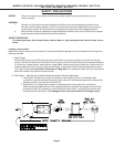
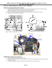
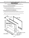
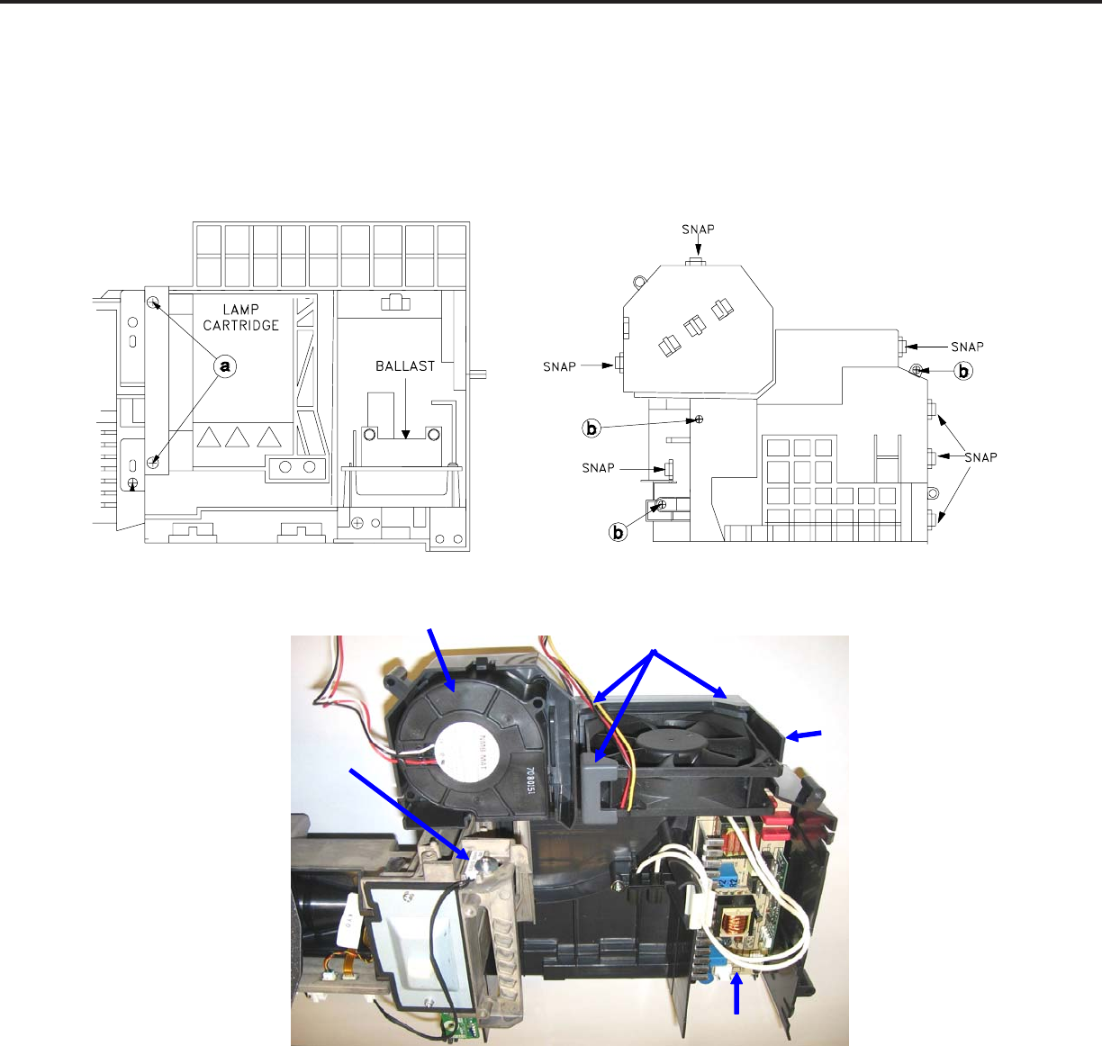
OPTICAL ENGINE REMOVAL FROM THE DUCT ASSEMBLY
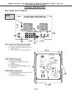
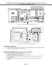
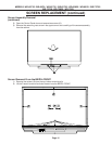
Figure 1: Duct Assembly (Rear View)
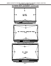
Figure 2: Duct Assembly (Top View)
Upper Duct Assembly Removal Procedure
1) Disconnect the Ballast Fan and Lamp Fan from the back of the Engine (connectors J4 and J8) and loosen
wiring harnesses from the looms, refer to page 11 for connector locations.
1) Loosen two screws (a) to remove the Lamp Cartridge, refer to Figure 1.
3) Remove 3 screws (b) from the top of the upper duct and release the 7 snaps shown in Figure 2.
4) Carefully remove the upper Duct assembly
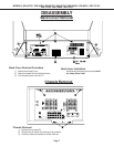
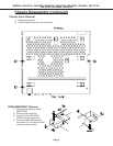
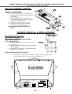
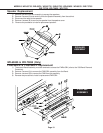
LOWER DUCT (Upper Duct Removed)
1) Figure 3 shows the components in the Lower Duct.
2) The Sirocco Fan and Exhaust Fan can be replaced. The Engine and Upper Duct do not have to be removed
to replace the Ballast.
3) If replacing the Engine, remove the Thermal Sensor from the Engine (1 screw) Figure 3.
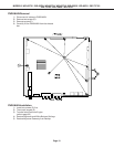
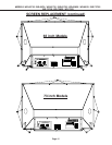
Figure 3: Lower Duct (Top View)
Ballast
Exhaust
Fan
Exhaust Fan
Holders (3)
Sirocco Fan
Thermal
Sensor